Performance Verification 1-15
CAUTION Before testing the 2Ω and 20Ω ranges, make sure your resistance calibrator
can safely handle the default test currents for those ranges (see Model 2430
and calibrator specifications). If not, use the CONFIG OHMS menu to se
-
lect the MANUAL source mode, then set the source current to an appro-
priate safe value. When using the manual source mode, total resistance
reading uncertainty includes both Source I and Measure V uncertainty
(see specifications), and calculated reading limits should take the addition
-
al uncertainty into account.
If using the Fluke 5450A resistance calibrator, you cannot use the Auto
Ohms mode of the Model 2430 to verify the 2¾ range. The 1A test current
for the 2¾ range of the Model 2430 will damage the calibrator. On the
Model 2430, use the CONFIG OHMS menu to select the MANUAL source
mode, and then set the source (test) current to 100mA.
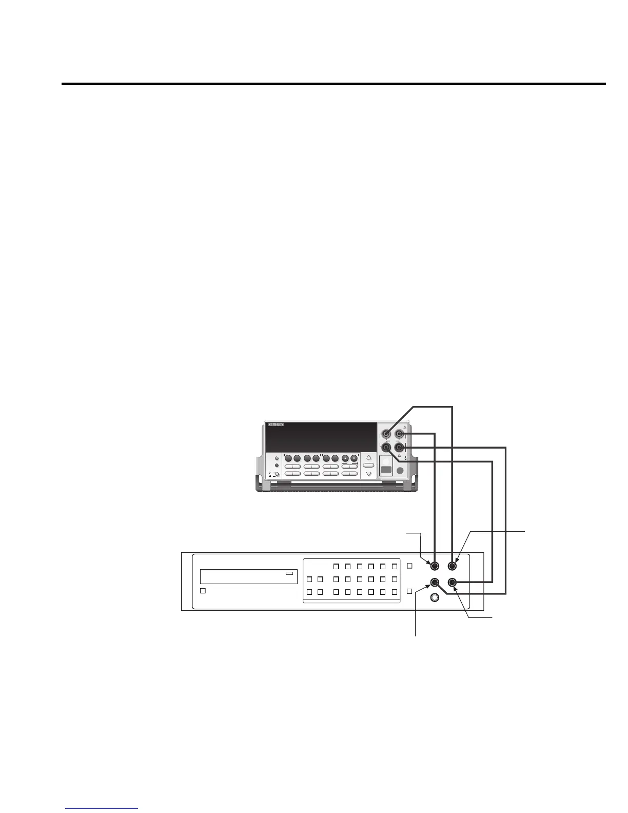
1. With the power off, connect the resistance calibrator to the Model 2430 INPUT/
OUTPUT and 4-WIRE SENSE jacks, as shown in Figure 1-4. Be sure to use the 4-wire
connections as shown.
Model 2430
Resistance Calibrator
Output HI
Sense HI
Output LO
Sense LO
2430 1KW PULSE SourceMeter
250V
PEAK
5V
PEAK
HI
LO
OUTPUT
125V
PEAK
125V
PEAK
EDIT
TOGGLE
POWER
RANGE
INPUT/
OUTPUT
4- WIRE
SENSE
DISPLAY
ON/OFF
TERMINALS
FRONT/
REAR
AUTO
RANGE
!
®
EXIT ENTER
CONFIG MENU
SWEEP
TRIG
REL
LOCAL
FILTER
LIMIT
DIGITS SPEED
V
Ω
MEAS
I
FCTN
V
I
SOURCE
230
1
67
89
4
+/-
5
STORE
RECALL
EDIT
Figure 1-4
Connections for
resistance accuracy
verification
2. Select the resistance calibrator external sense mode.
 Loading...


