5-4 Disassembly
2. Remove mounting ears — Remove the screw that secures each mounting ear. Pull
down and out on each mounting ear.
NOTE When re-installing the mounting ears, make sure to mount the right ear to the
right side of the chassis, and the left ear to the left side of the chassis. Each ear is
marked “RIGHT” or “LEFT” on its inside surface.
3. Remove rear bezel — To remove the rear bezel, loosen the two screws that secure the
rear bezel to the chassis, then pull the bezel away from the case.
4. Remove grounding screws — Remove the two grounding screws that secure the case
to the chassis. They are located on the bottom of the case at the back.
5. Remove chassis — To remove the case, grasp the front bezel of the instrument, and
carefully slide the chassis forward. Slide the chassis out of the metal case.
NOTE To gain access to the components under the analog board shield, remove the
shield, which is secured to the analog board by a single screw.
Analog board removal
Perform the following steps to remove the analog board. This procedure assumes that the case
cover is already removed.
1. Remove the small pulse board before removing the analog board.
2. Disconnect the front and rear input terminals.
You must disconnect these input terminal connections for both the front and rear inputs:
• INPUT/OUTPUT HI and LO
• 4-WIRE SENSE HI and LO
•V, Ω, GUARD and GUARD SENSE (rear panel only)
Remove all the connections by pulling the wires off the pin connectors, then remove the fer-
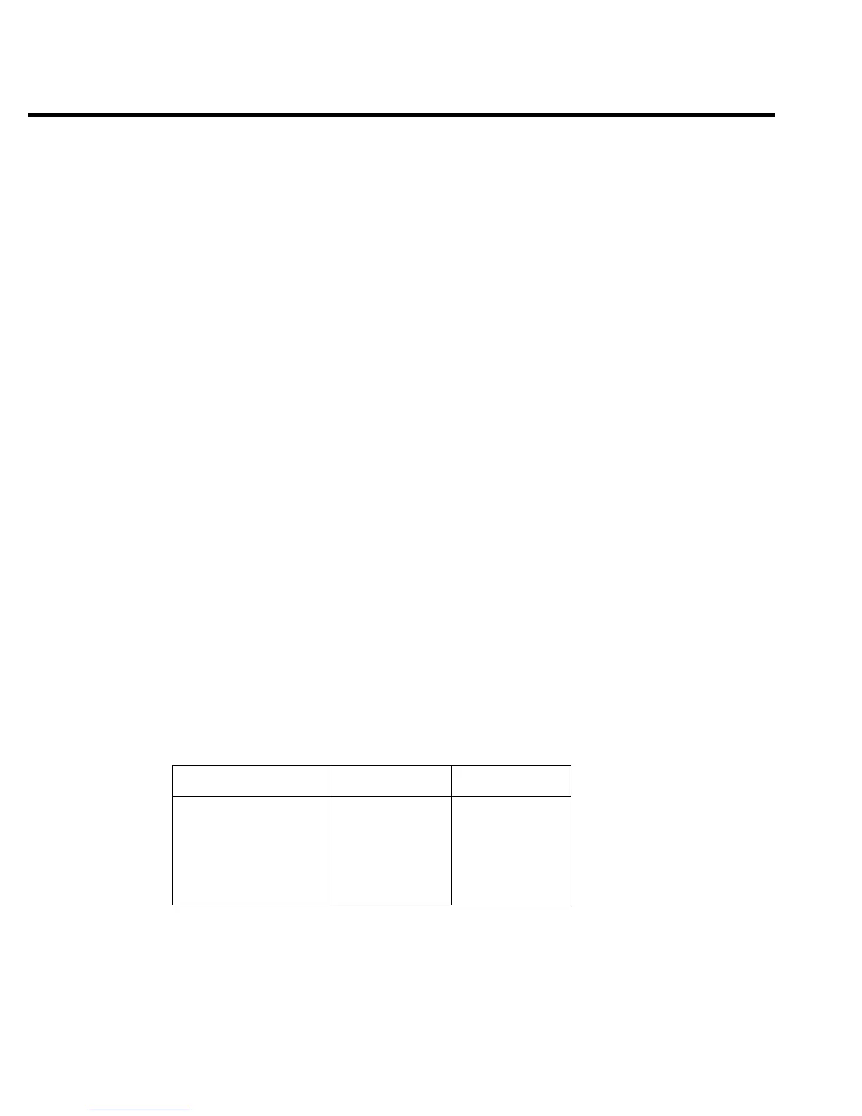
rite noise filters from the chassis. During re-assembly, use the following table to identify input
terminals:
Input terminals Front wire color Rear wire color
INPUT/OUTPUT HI
INPUT/OUTPUT LO
4-WIRE SENSE HI
4-WIRE SENSE LO
V, Ω, GUARD
GUARD SENSE
Red
Black
Yellow
Gray
-
-
White/Red
White/Black
White/Yellow
White/Gray
White
Blue/White
3. Unplug cables.
• Carefully unplug the ribbon cables at J1027, J1028, and J1029.
• Unplug the ON/OFF cable at J1034.
 Loading...


