3-2 Routine Maintenance
Introduction
The information in this section deals with routine type maintenance that can be performed by
the operator.
Line fuse replacement
WARNING Disconnect the line cord at the rear panel, and remove all test leads con-
nected to the instrument (front and rear) before replacing the line fuse.
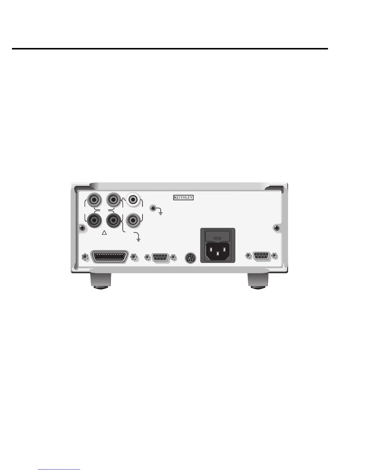
The power line fuse is accessible from the rear panel, just above the AC power receptacle
(Figure 3-1).
CAUTION:FOR CONTINUED PROTECTION AGAINST FIRE HAZARD,REPLACE FUSE WITH SAME TYPE AND RATING.
CAUTION:FOR CONTINUED PROTECTION AGAINST FIRE HAZARD,REPLACE FUSE WITH SAME TYPE AND RATING.
MADE IN
U.S.A.
INPUT/
OUTPUT
250V
PEAK
125V
PEAK
TRIGGER
LINK
4-WIRE
SENSE
LO
LINE RATING
100-240VAC
50, 60HZ
250VA MAX
RS232
IEEE-488
(ENTER IEEE ADDRESS
WITH FRONT PANEL MENU)
125V
PEAK
5V
PEAK
5V
PEAK
5V
PK
V, Ω,
GUARD
GUARD
SENSE
LINE FUSE
SLOWBLOW
3.15A, 250V
OUTPUT
ENABLE
HI
WARNING:NO INTERNAL OPERATOR SERVICABLE PARTS,SERVICE BY QUALIFIED PERSONNEL ONLY.
WARNING:NO INTERNAL OPERATOR SERVICABLE PARTS,SERVICE BY QUALIFIED PERSONNEL ONLY.
Figure 3-1
Rear panel
Perform the following steps to replace the line fuse:
1. Carefully grasp and squeeze together the locking tabs that secure the fuse carrier to the
fuse holder.
2. Pull out the fuse carrier, and replace the fuse with the type specified in Table 3-1.
CAUTION To prevent instrument damage, use only the fuse type specified in Table 3-
1.
3. Re-install the fuse carrier.
 Loading...


