Troubleshooting 4-5
Overall block diagram
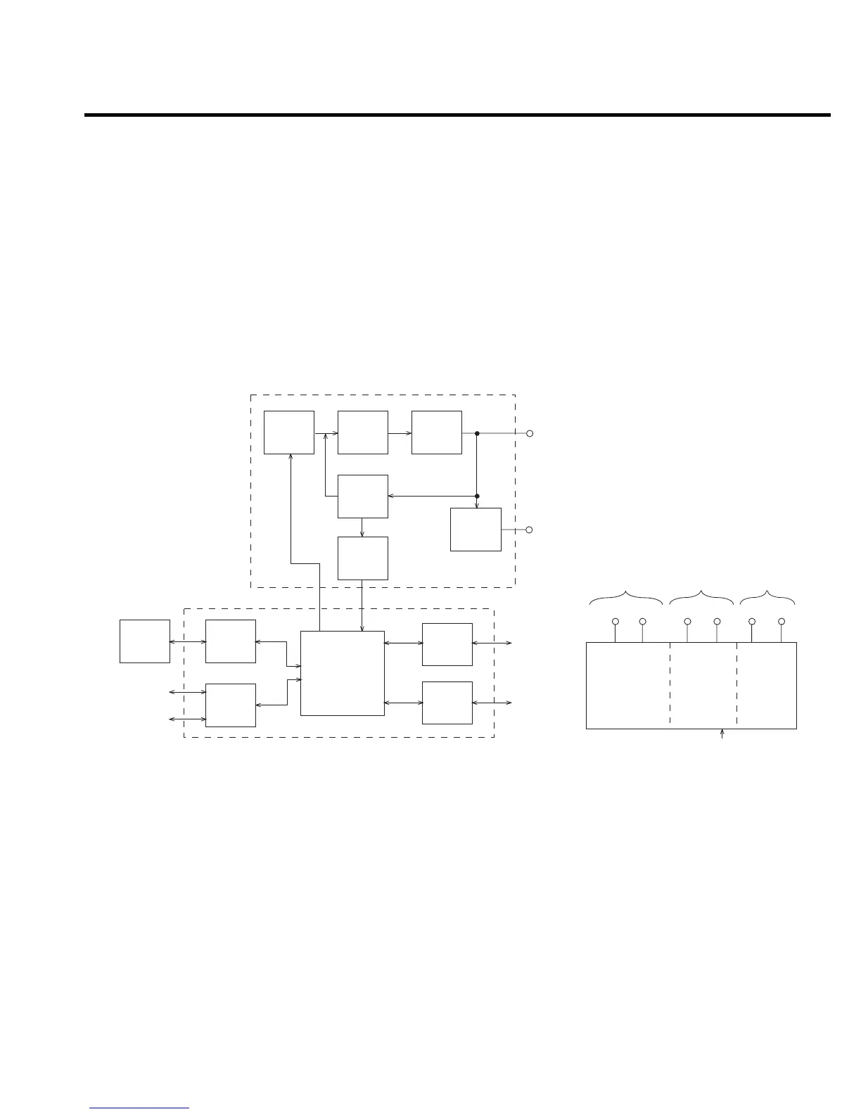
Figure 4-1 shows an overall block diagram of the Model 2430. Circuitry may be divided into
three general areas:
• Analog circuits — includes sourcing circuits such as the DACs, clamps, output stage,
and feedback circuits, as well as measurement circuits such as the A/D converter.
• Digital circuits — includes the microcomputer that controls the analog section, front
panel, and GPIB and RS-232 ports, as well as associated interfacing circuits.
• Power supplies — converts the AC line voltage into DC voltages that supply the power
for the digital and analog circuits, and the output stage.
Analog Section
Output
A/D
Converter
Guard
Buffer
Guard
Display,
Keyboard
Microcomputer
Digital
I/O
GPIB
Interface
RS-232 I/O
GPIB I/O
Digital Section
To Analog
Circuits
To
Output Stage
To
Digital Circuits
±15V
+5V ±42V
±150V +5V +12V
Analog
Power
Supply
Output
Stage
Power
Supply
Digital
Power
Supply
Line In
Power Supply
DACs
Clamps
Output
Stage
Feedback
Front
Panel
Controller
Trigger,
Digital
I/O
RS-232
Trigger
Link
Figure 4-1
Overall block
diagram
 Loading...


