2600S-901-01 Rev. C / January 2008 Return to Section Topics 10-15
Series 2600 System SourceMeter® Instruments Reference Manual Section 10: Digital I/O and Triggering
Hardware trigger modes
Use the hardware trigger modes to integrate Keithley Instruments and non-Keithley instruments
into an efficient test system. The hardware synchronization lines are classic trigger lines. The
Series 2600 contains 14 digital I/O lines and three TSP-Link synchronization lines that you can use
for input or output triggering.
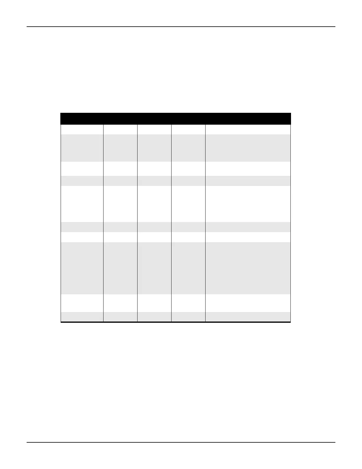
Table 10-5 provides a summary for each hardware trigger mode.
Table 10-5
Hardware trigger mode summary
Trigger mode Output Input Notes
Unasserted Asserted Detects
Bypass N/A N/A N/A
Use the writebit and
writeport commands for direct
line control (Version 1.4.0 and
higher).
Either Edge High Low Either
Short input pulses can cause a
trigger overrun.
Falling Edge High Low Falling
Rising Edge N/A N/A N/A
Rising A High Low Rising
RisingM Low High None
Synchronous
High
latching
Low Falling
SynchronousA
High
latching
High Falling
Ignores the pulse duration.
SynchronousM High Low Rising
Each trigger mode controls the input trigger detection and output trigger generation. The input
detector monitors for and detects all edges, even if the node that generates the output trigger
causes the edge.
A trigger overrun generates if an input trigger is received before the previous input trigger
processes. To determine if a trigger overrun has occurred, reference the trigger overrun attributes.
For additional information on the hardware trigger modes, see “Instrument Control Library” on
page 12-1 for more information.
• The programmed state of the line
determines if the behavior is
similar to RisingA or RisingM
•High similar to RisingA
•Low similar to RisingM
• Behaves similar to
SynchronousA
• Trigger overrun detection is
disabled
• To mirror the SynchronousA
trigger mode, set the pulse
duration to 1µs or any small
nonzero value

 Loading...


