1-12 Return to Section Topics 2600S-901-01 Rev. C / January 2008
Section 1: Getting Started Series 2600 System SourceMeter® Instruments Reference Manual
1. CHANNEL A and CHANNEL B (Channel B on Model 2636 only)
Triax connectors for input/output, guard, and sense connections. Use only low-noise triax cables such as
the Keithley Instruments Model 7078-TRX (available in several lengths). Connector terminals and
associated triax cable conductors are as follows:
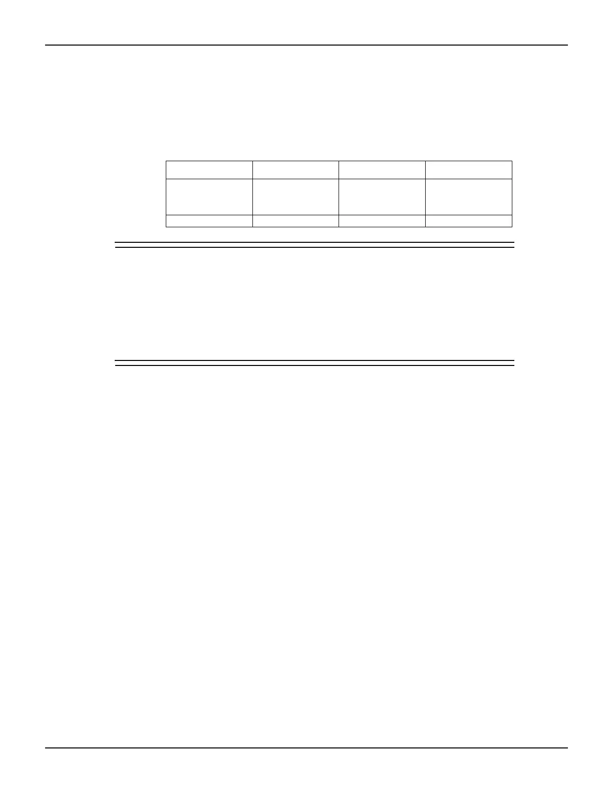
Table 1-1
Connectors and triax cable conductors
Connector Center conductor Inner ring Outer ring
LO Sense LO Input/Output LO Chassis ground
HI Input/Output HI Guard Chassis ground
SENSE HI Sense HI Guard Chassis ground
Triax cable Center conductor Inner shield Outer shield
WARNING When connecting to the model 2611, 2612, 2635 and 2636 SMU
outputs, with cables not rated for voltages above 42V, such as the
2600-ALG-2, you must disable the high voltage output by using the
INTERLOCK function as defined in section 10 of this manual.
Leaving the high voltage enabled while not properly insulating the
external connections to the unit poses a shock hazard which could
cause serious injury to the user. It is also recommended that the
LO connection terminal not be allowed to float by connecting it to
signal ground or another known signal reference.
2. DIGITAL I/O
Female DB-25 connector. Fourteen pins for digital input or output, one pin for safety interlock. Use a cable
equipped with a male DB-25 connector (Keithley Instruments part number CA-126-1CA).
3. IEEE-488
Connector for IEEE-488 (GPIB) operation. Use a shielded cable, such as the Model 7007-1 or Model
7007-2.
4. Cooling exhaust vent
Exhaust vent for internal cooling fan. Keep vent free of obstructions to prevent overheating.
5. Chassis ground
Ground screw for connections to chassis ground.
6. RS-232
Female DB-9 connector. For RS-232 operation, use a straight-through (not null modem) DB-9 shielded
cable for connection to the PC (Keithley Instruments Model 7009-5).
7. TSP-Link
Expansion interface that allows a Series 2600 and other TSP-enabled instruments to trigger and
communicate with each other. Use a category 5e or higher LAN crossover cable (Keithley Instruments
part number CA-180-3A).
8. Power module
Contains the AC line receptacle and power line fuse. The instrument can operate on line voltages of 100V
to 240VAC at line frequencies of 50Hz or 60Hz. See
Section 17 of this manual for line fuse replacement
instructions.

 Loading...


