System Switch/Multimeter User's Manual Section 9:
Series 3700 Module Schematics and Connections
-900-01 Rev. A / August 2007 9-
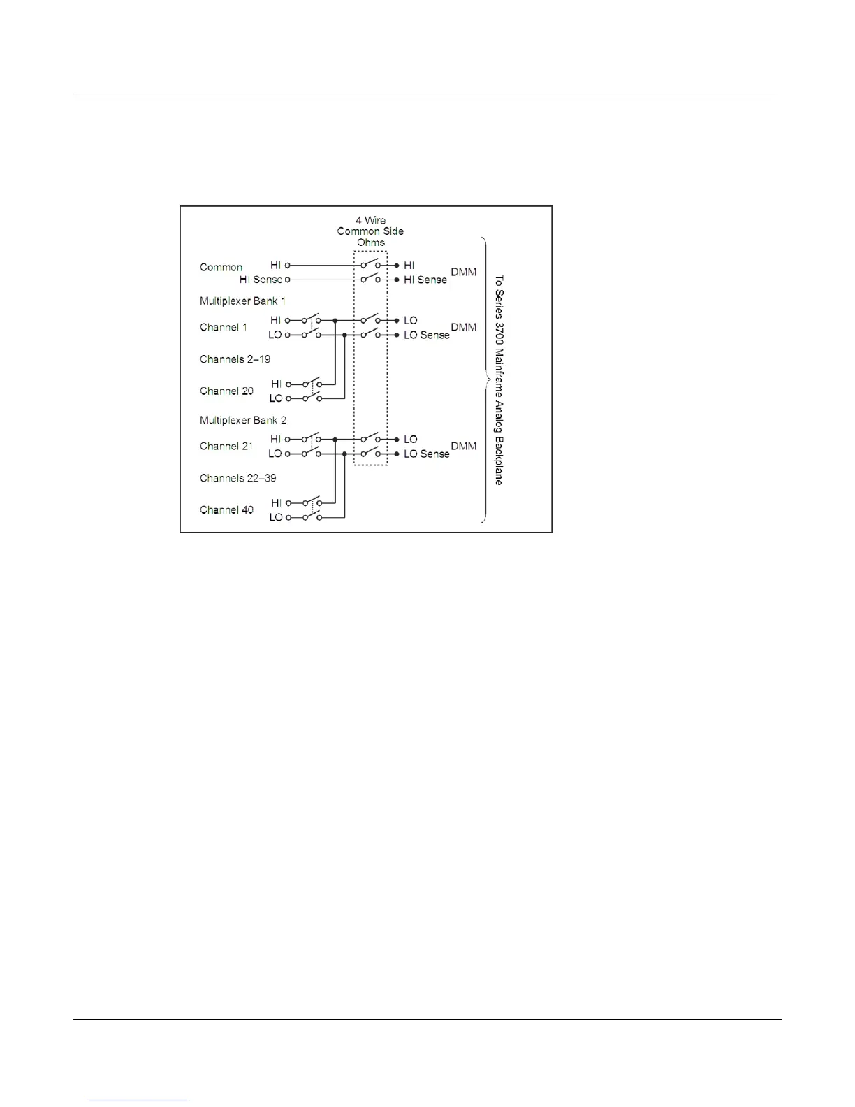
The following figure provides a switching schematic for the Model 3721 in four-wire common
side ohm mode.
Figure 9-9: Schematic of the Model 3721 in four-wire common side ohm mode
Model 3721: AMPS channels fuse replacement
Channels 41 and 42 are protected by series fuses. In the event of an overload, both channels
and the DMM input are protected. The two fuses are replaceable and are located on the printed
circuit board of the Model 3721 switch card. The Model 3721 must be removed from the Series
3700 and all power disconnected in order to access these fuses.
 Loading...


