System Switch/Multimeter User's Manual Section 5:
Basic Digital Multimeter (DMM) Operation
-900-01 Rev. A / August 2007 5-
Switching module
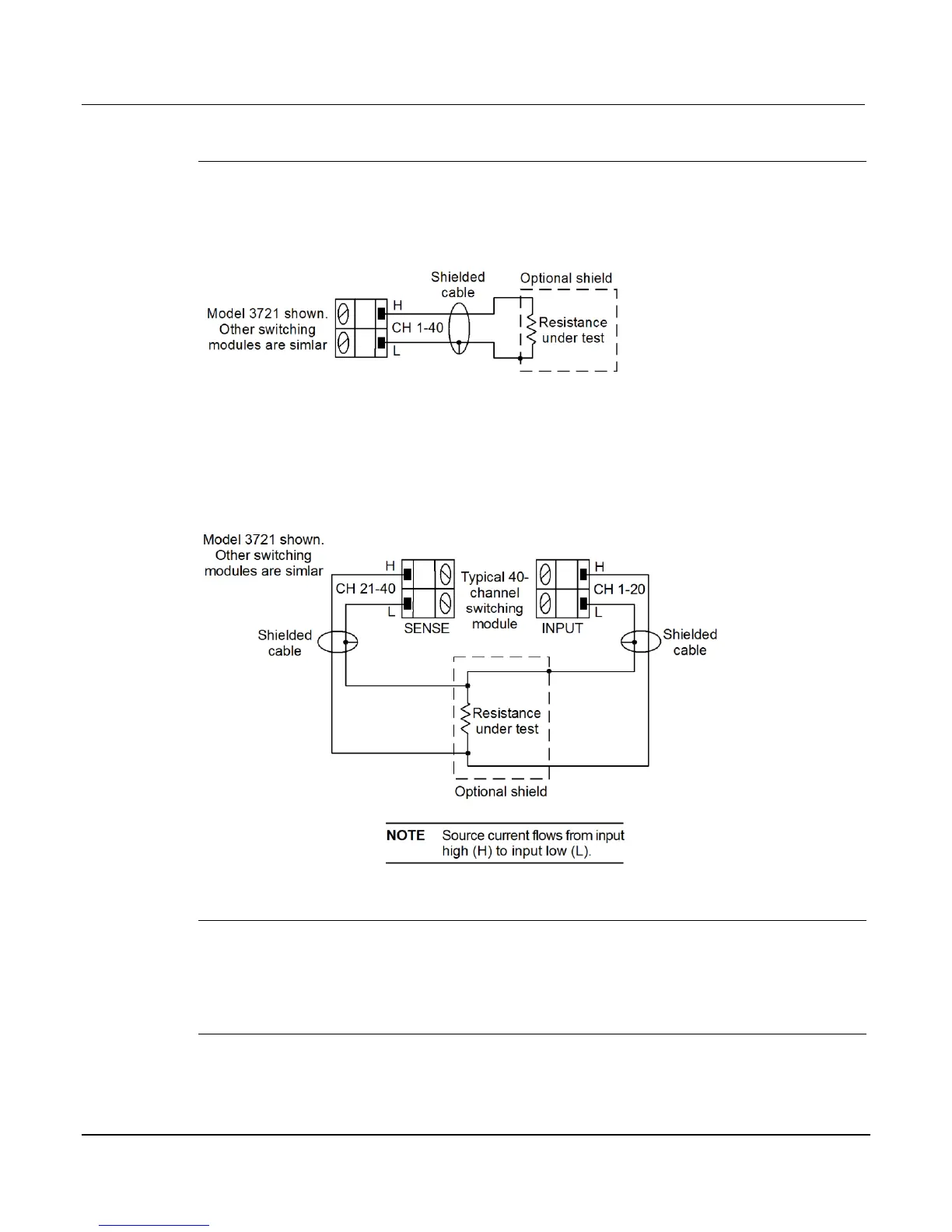
Connections for the switching module are shown below. As shown, each of the 40 channels can
be used to perform 2W measurements.
Figure 5-9: Two-wire switching module resistance connection
For 4W measurements, a channel pair is used for each 4-wire measurement as shown. For
4W connections on a 40-channel switching module, Channels 1 through 20 (which are used as
the INPUT terminals) are paired to Channels 21 through 40 (which are used as the SENSE
terminals). Channel 1 is paired to Channel 21, Channel 2 is paired to Channel 22, and so on.
Figure 5-10: Four-wire switching module resistance connection
Shielding
To achieve a stable reading, it helps to shield resistances greater than 100k. As shown in
analog backplane connector (rear panel) (on page 5-17), place the resistance in a shielded
enclosure and connect the shield to the INPUT LO terminal of the instrument electrically.
Cable leakage
For high resistance measurements in a high humidity environment, use Teflon™ insulated
cables to minimize errors due to cable leakage.
 Loading...


