4: Closing and Opening Switching Module Channels Series 3700 System Switch/Multimeter
-14 Document Number: 3700S-900-
2-wire functions
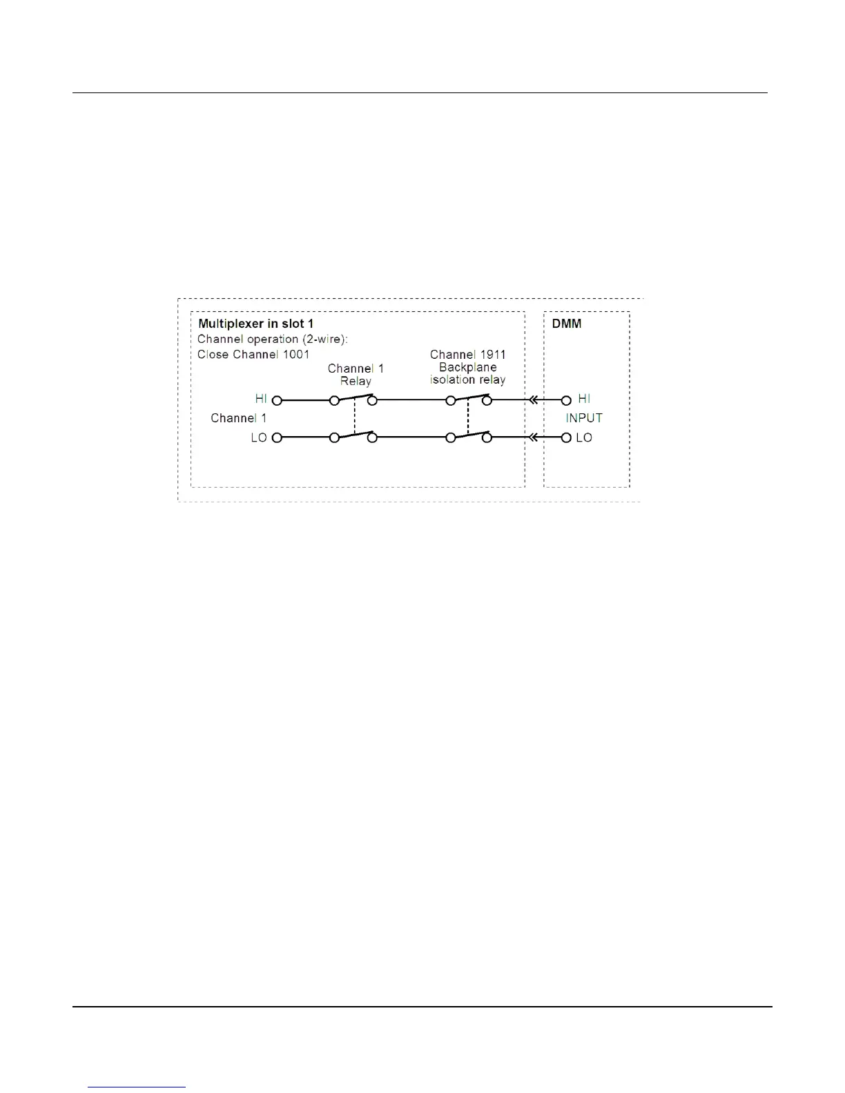
The following figure shows an example of how the channel is connected to the DMM Input of the
Series 3700 with regards to a 2-wire function, such as DC volts. Assume a switching module
with 20 channels is installed in Slot 1 of the mainframe. When Channel 1001 is closed using the
channel Close key, both the Channel 1 relay and the backplane isolation relay (Channel 1911)
close to connect the channel to the DMM.
Figure 4-3: Two-wire function
4-wire functions (paired channels)
A 4-wire function, such as Ω4, requires that another measurement channel (SENSE) be paired
to the channel (INPUT). For example, in a switching module that has 20 measurement channels,
Channels 1 through 10 can be used as the calling channels (channels that are sent with the
commands or closed from the front panel), while Channels 11 through 20 are used as the paired
channel. For a switching module that has 20 measurement channels, Channel 1 is paired to
Channel 11, Channel 2 is paired to Channel 12, Channel 3 is paired to Channel 13, and so on.
The following figure shows an example of channel connections for a 4-wire function.
 Loading...


