System Switch/Multimeter User's Manual Section 5:
Basic Digital Multimeter (DMM) Operation
-900-01 Rev. A / August 2007 5
Schematic
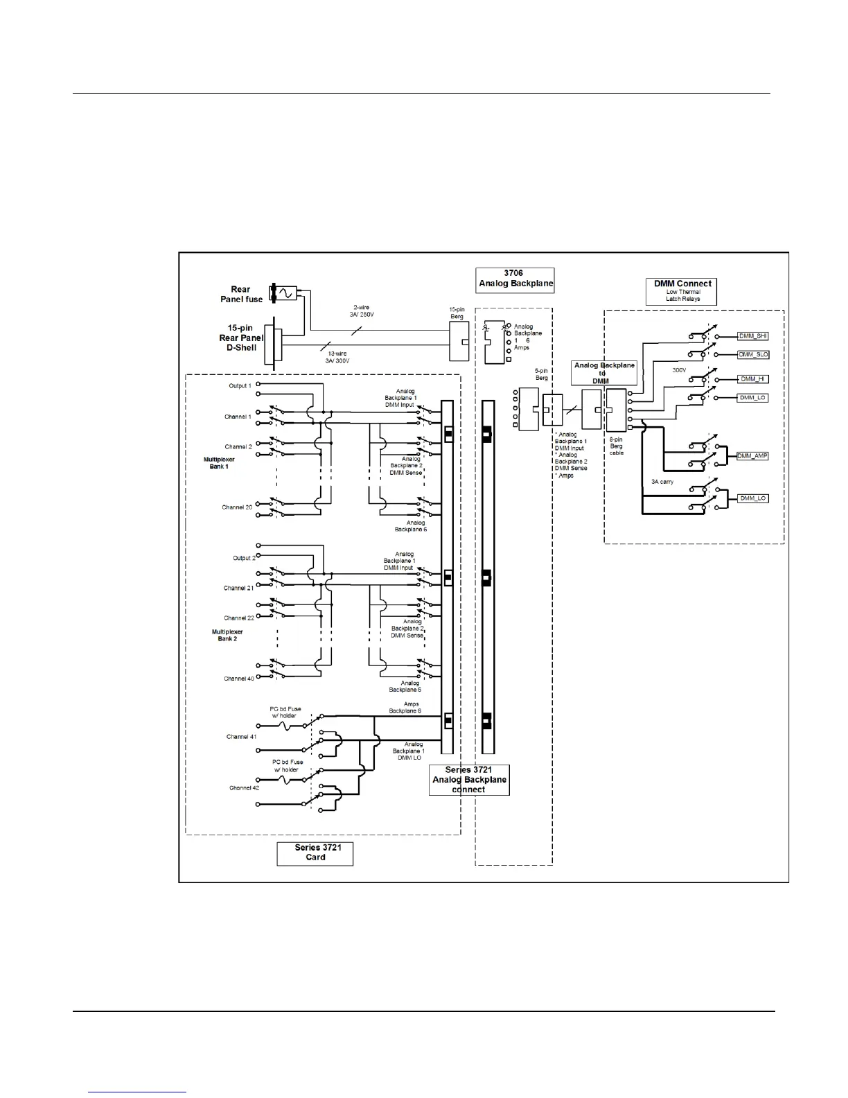
Refer to the following figure for a schematic of the rear panel, backplane, and DMM connect
relays with a typical card.
Figure 5-4: Rear panel to backplane to DMM connect relays schematic
 Loading...


