System Switch/Multimeter User's Manual Section 5:
Basic Digital Multimeter (DMM) Operation
-900-01 Rev. A / August 2007 5-
Continuity testing connections
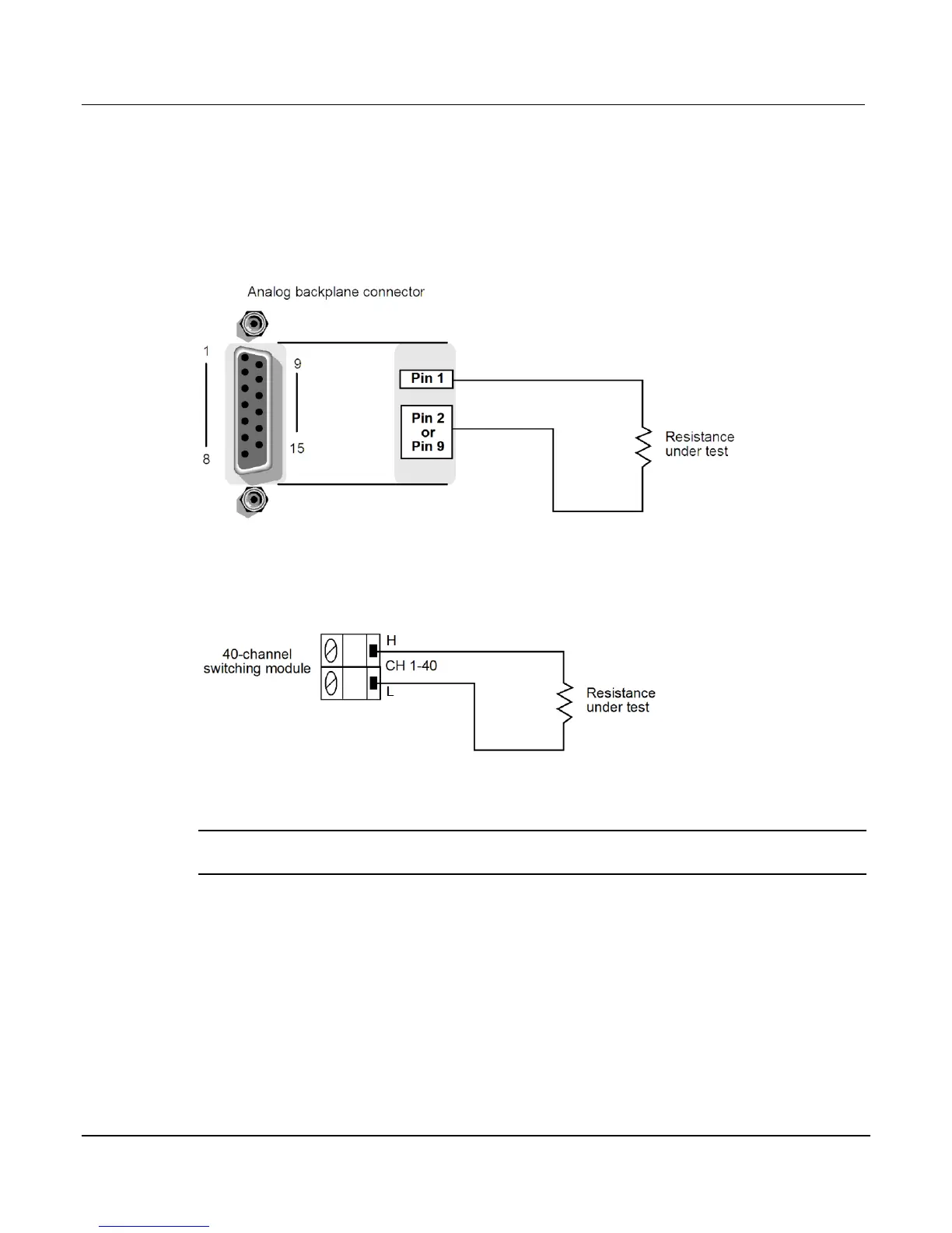
When using the rear analog backplane connector, connect the test leads to the INPUT HI and
LO terminals as shown below.
Figure 5-34: Continuity connections
Connections to test continuity using a switching module are shown below. Since this is a 2-wire
ohms measurement, Channels 1 through 20 of a 40-channel switching module can be used.
Figure 5-35: Continuity connections using a switching module
Continuity testing procedure
NOTE If the Series 3700 is in remote, place the unit in local by pressing the LOCAL key (or
the EXIT key).
1. Press the OPENALL key to open all switching channels.
2. Select the continuity testing function by pressing the FUNC key until "CNT" is displayed.
3. Press the CONFIG key and then the DMM key. The "CONT ATTR MENU" will open.
 Loading...


