System Switch/Multimeter User's Manual Section 3:
-900-01 Rev. A / August 2007 3
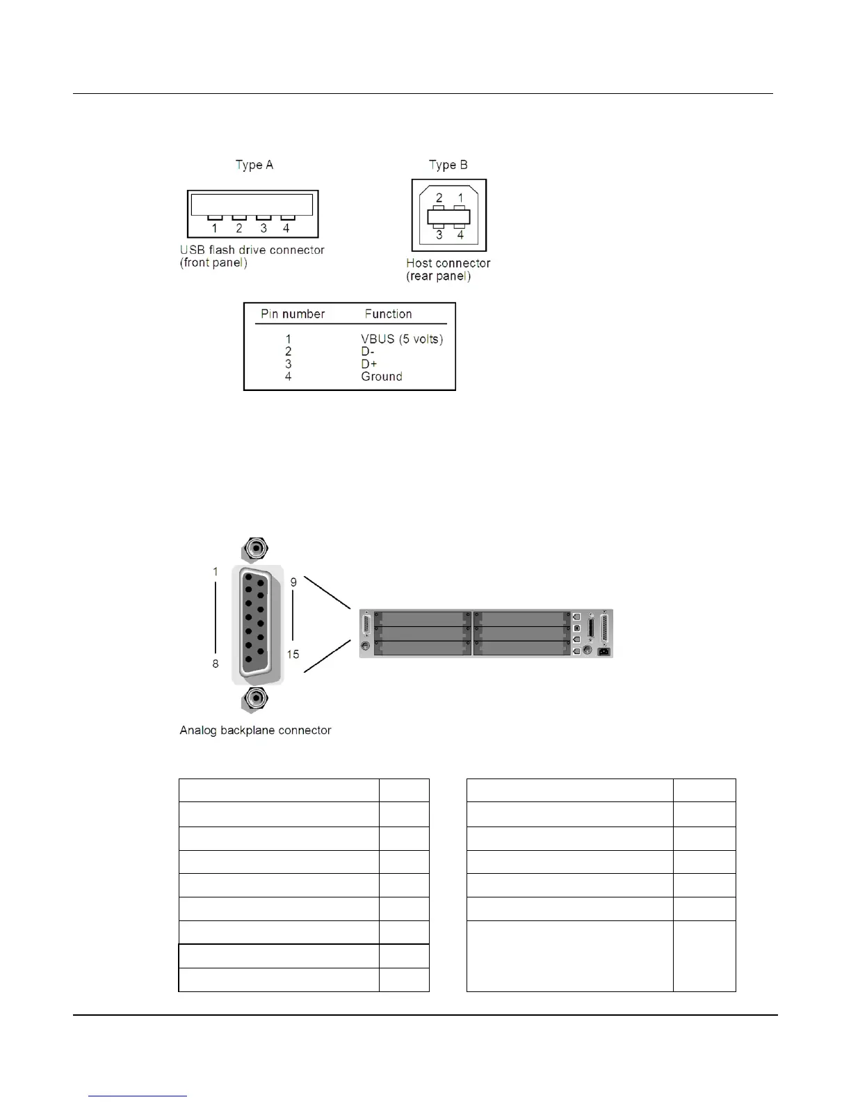
Figure 3-3: USB connectors
Analog backplane connector
Refer to the following figure for analog backplane connector information. See Connections (on
page 3-8) before making any connections.
Figure 3-4: Analog backplane connector
The table below contains pin numbers and descriptions for the analog backplane connector.
-HI
-SLO
-LO
-SHI
-HI
-LO
-LO
-HI
-LO
-LO
-LO
 Loading...


