TP-5737 5/01 5Section 2 Operation
Section 2 Operation
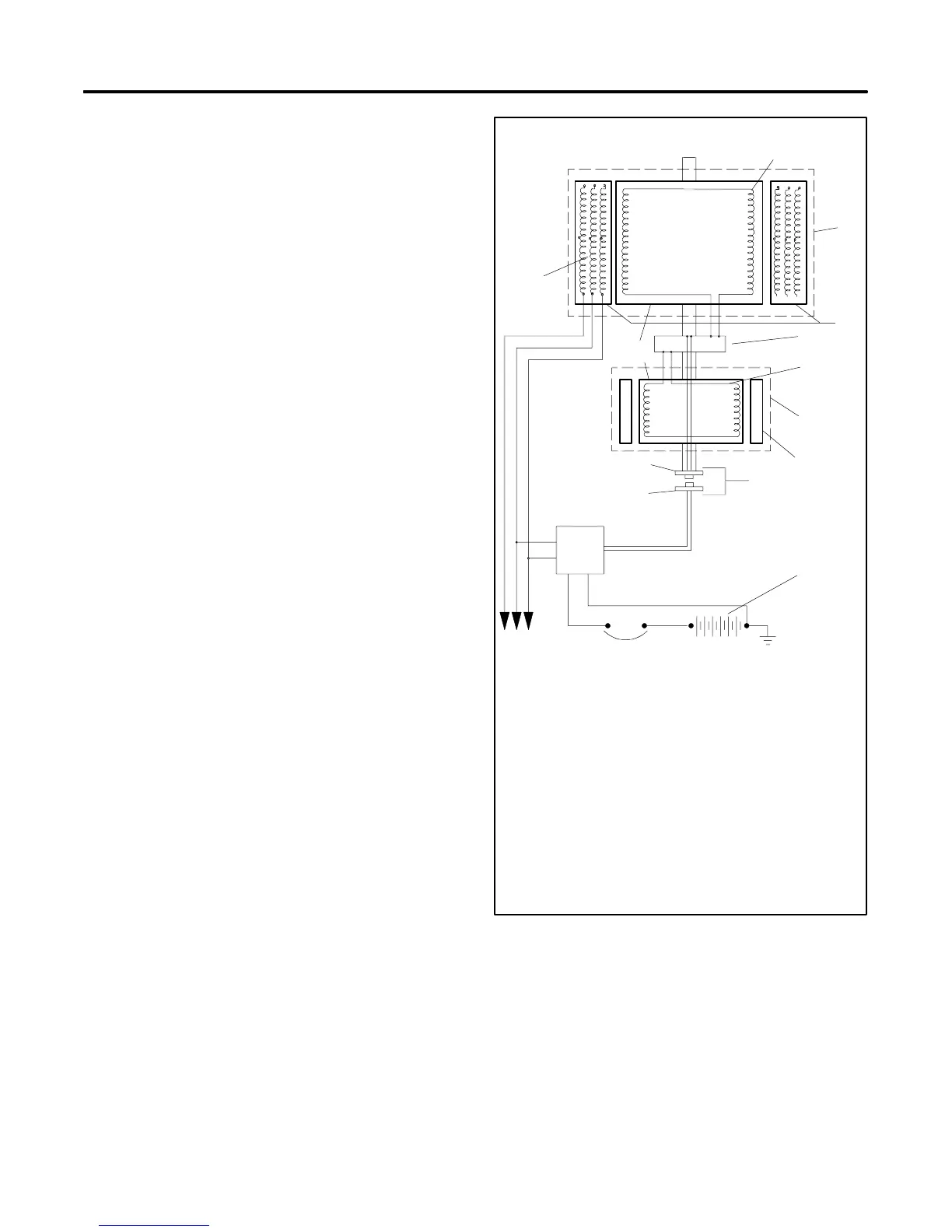
2.1 Fast-Responset II Concepts
The generator excitation system uses a permanent
magnet exciter with a silicon controlled rectifier (SCR)
assembly that controls the amount of DC current fed to
the generator field. This type of system uses a voltage
regulator that signals the SCR assembly through an
optocoupler. The voltage regulator monitors generator
output voltage and engine speed and signals the SCR
assembly to turn on or off accordingly through the
optocoupler. The optical coupler consists of a light
emitting diode (LED) mounted on the stationary end
bracket and a photo transistor mounted on the rotating
shaft. The photo transistor picks up the infrared signal
from the LED and signals the SCR assembly to turn on
or off, depending upon the need, as dictated by the
voltage regulator. See Figure 2-1.
The voltage recovery period of this type of generator is
several times faster than the conventionally wound field
brushless generator because the generator set does not
have to contend with the inductance of the exciter field.
The generator set also has better recovery
characteristics than the static-excited machine because
it is not dependent upon the generator set output voltage
for excitation power. Possibly the greatest advantage of
this type of machine is its inherent ability to support
short-circuit current and allow system coordination for
tripping downstream branch circuit breakers.
The generator set systems deliver exciter current to the
main field within 50 milliseconds (0.050 seconds) of a
change in load demand.
2.2 Short Circuit P erformance
When a short circuit occurs in the load circuit(s) being
served, output voltage drops and amperage
momentarily rises to 600--1000% of the generator set’s
rated current until removal of the short. The SCR
assembly sends full exciter power to the main field. The
generator then sustains up to 300% of its rated current.
Sustained high current causes correspondingly rated
load circuit fuses/breakers to trip. The safeguard
breaker kit shuts down the excitation system in the event
of a sustained heavy overload or short circuit.
1
2
3
4
6
7
8
9
10
11
12
13
5
TP-5353-1
14
15
16
1. Main armature
2. Main field
3. Main generator
4. Stator
5. SCR assembly
6. Exciter armature
7. Rotor
8. Exciter generator
9. Exciter field magnets
10. Optical coupler
11. LED board (PCB assembly)
12. Photo transistor board (PCB assembly)
13. AC voltage regulator
14. Starting battery
15. Safeguard breaker (optional)
16. Main output leads
Figure 2 -1 Alternator Schematic
 Loading...
