TP-5737 5/01 9Section 2 Operation
Name Description
Auxiliary prealarm
lamp
The lamp illuminates when
customer-provided sensing
devices activate the pump.
Emergency stop
lamp
The lamp illuminates and the
generator set shuts down when
energizing the optional emergency
stop switch. The lamp needs the
optional emergency stop switch to
function.
Generator switch not
in auto lamp
The lamp illuminates when the
generator set master switch is in
the RUN or OFF/RESET position.
Low fuel lamp The lamp illuminates when the fuel
level in the tank approaches
empty. The lamp needs a low fuel
sensor in the fuel tank to function.
High water
temperature lamp
The lamp illuminates when the
water temperature approaches
shutdown range. The lamp needs
an optional prealarm sender kit to
function.
Prealarm high engine
temperature lamp
The lamp illuminates when the
engine coolant temperature
approaches shutdown range. The
lamp needs an optional prealarm
sender kit to function.
Prealarm low oil
pressure lamp
The lamp illuminates when the
engine oil pressure approaches
shutdown range. The lamp needs
an optional prealarm sender kit to
function.
System ready lamp The lamp illuminates when the
generator set master switch is in
AUTO position and the system
senses no faults.
Emergency stop
switch
The switch, if activated, instantly
shuts down the generator set in
emergency situations. Use the
emergency stop switch for
emergency shutdowns only. Use
the generator set master switch for
normal shutdowns.
2.7.2 Fuses and Terminal Strips
The following table describes the controller circuit board
fuses and controller terminal strips.
Name Description
3-amp remote
annunciator fuse
The fuse protects the remote
annunciator circuit, A/V alarm, and
isolated alarm kit, if equipped.
3-amp controller fuse The fuse protects the controller
circuit board, speed sensor, and
lamp circuit board.
15-amp engine and
accessories fuse
Thefuseprotectsthe
engine/starting circuitry and
accessories.
Controller TB1
terminal strip
The terminal strip provides
connection points for
customer-supplied sensing
devices and generator set
accessories such as the
emergency stop switch, remote
start stop/switch, audio/visual
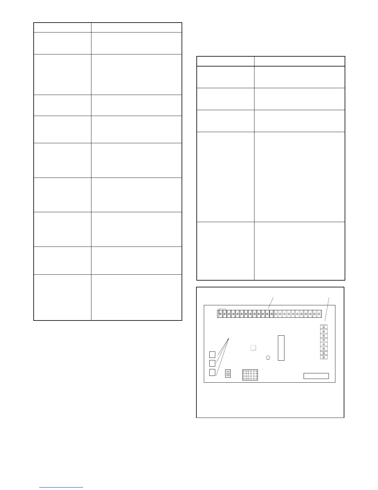
alarms, etc., to the controller.
Figure 2-4 shows the location of
the TB1 terminal strip on the
controller circuit board. Refer to
the wiring diagrams for information
on connecting accessories to the
TB1 terminal strip.
Controller TB2
terminal strip
The terminal strip provides
connection points for crank mode
selection (cyclic or continuous)
and remote start/stop switch inputs
of operation. Figure 2-4 shows the
location of the TB2 terminal strip
on the controller circuit board.
Refer to the wiring diagrams for
connection information.
P1
P2
A-336415-A
R41
LED4
12
3
1. TB1 terminal strip
2. TB2 terminal strip
3. Fuses
Figure 2 -4 TB1 and TB2 Terminal Strips on
Decision-Makert 3+ Controller Circuit
Board
 Loading...
