TP-5737 5/01 23Section 5 Decision-Makert 3+ Troubleshooting
Section 5 Decision-Makert 3+ Troubleshooting
5.1 Decision-Makert 3+ Controller
For external features, see Section 2, Operation.
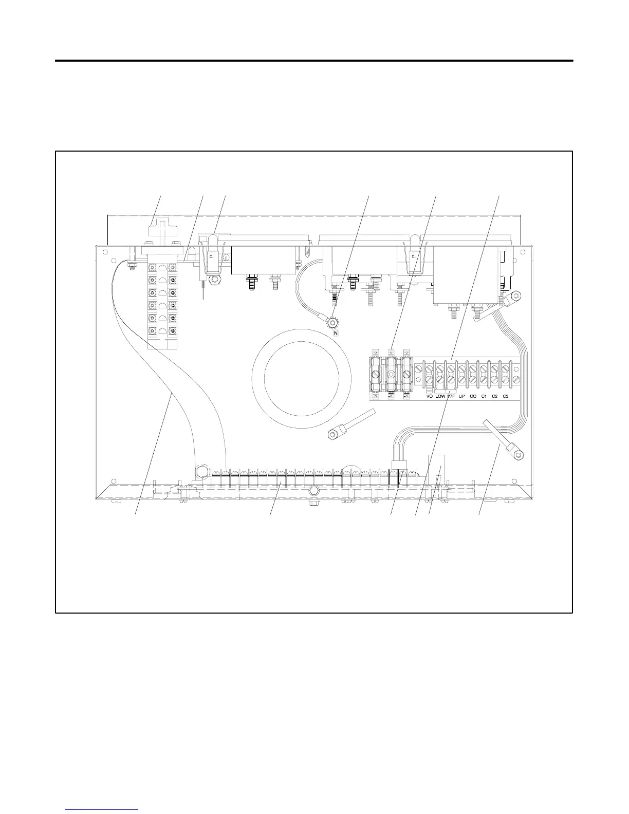
Figure 5-1 through Figure 5-11 show the locations of
controller components and connections. Figure 5-12
contains the logic schematic showing input/output
circuits for reference in troubleshooting. This
information deals directly with the 16-light
microprocessor.
1
10 9
625
11 7
3
12
4
8
A-328917-X
1. Selector switch
2. Lamp circuit board
3. Panel lamps
4. Controller DC ground terminal
5. AC fuse terminal block (TB3)
6. CT/meter scale terminal block (TB2)
7. Accessory wire guide loops
8. Controller fuses
9. Lamp selection jumper
10. Control panel harness connector (P2)
11. Controller main circuit board
12. P3/P4 harness
Figure 5 -1 Decision-Makerä 3+ Controller
 Loading...
