TP-5737 5/0140 Section 5 Decision-Makert 3+ Troubleshooting
Switches:
D LOP—low oil pressure
D HWT—high water (engine) temperature
D OVERSPEED—simulates a 70 Hz overspeed
condition
D LF—low fuel (not used for testing)
D LWT—low engine water temperature
D AOP—anticipatory (low) oil pressure
D AWT—anticipatory (high) water temperature
5.4.2 Application
Use the FASTCHECK
â
to test the microprocessor
controller on the generator set when troubleshooting
startup problems or to test and troubleshoot the
controller when removed from the generator set.
To operate the FASTCHECK
â
the following equipment
is required:
D FASTCHECK
â
simulator (B-291930) and harness
(255915).
D Variable low-voltage DC power supply; 0--30 volt,
3 amp minimum current, 0.5% maximum output
voltage ripple at 30 volts DC. A 12- or 24-volt battery
(depending on system voltage) can also be used to
operate the FASTCHECK
â
.
5.4.3 Connect/Operate Procedure
Use the following procedure to connect/operate the
FASTCHECK
â
tester.
Procedures to test the overcrank circuitry, speed sensor
circuitry, and generator condition indicators are
described later in this section.
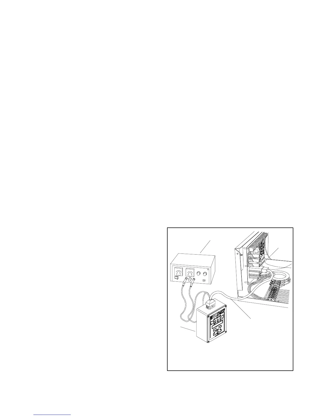
1. Unplug the DC engine harness from the DC
harness connector (P1). See Figure 5-28.
2. Connect the FASTCHECK
â
harness to the DC
harness connector (P1) and to the top of the
FASTCHECK
â
.
3. Move the generator set master switch to the
OFF/RESET position.
4. Move the FASTCHECK
â
engine switch to the OFF
position.
5. Clip the red (+) and black (--) harness leads to a
battery(ies) or DC power supply of proper voltage
for the generator set (12 or 24 volts). Adjust the
output voltage to 1-2 volts above battery voltage
when using a DC power supply. See the BATT
rating on the generator nameplate. Use the
generator set battery(ies) if accessible and fully
charged.
Note: Observe the correct polarity when
connecting FASTCHECK
â
, otherwise
circuit board damage occurs.
Note: Because of the absence of AC output, the
auxiliary lamp flashes during controller
testing (on 16-light microprocessor
controllers). The NOT-IN-AUTO lamp
illuminates whenever the generator set
master switch is not in the AUTO position on
16-light microprocessor controllers.
6. Move the generator set master switch to the RUN
position. Move the FASTCHECK
â
engine switch
to the CRANK position. The FASTCHECK
â
IGN,
CRK, and REG lamps should light. The generator
controller causes the engine to crank until the
FASTCHECK
â
switch is moved to the RUN
position (or OVERCRANK shutdown appears on
generator controller).
7. Move the FASTCHECK
â
engine switch to the RUN
position. CRK lamp should go out and REG and
IGN lamps should stay on.
1
2
3
4
R11118 -2
3-187
1. FASTCHECKâ
2. Wiring harness
3. DC harness connector
4. DC power supply
Figure 5 -28 FASTCHECK
â
Connections
 Loading...
