TP-5737 5/01 25Section 5 Decision-Makert 3+ Troubleshooting
5.1.1 Decision-Maker 3+ Circuit Board
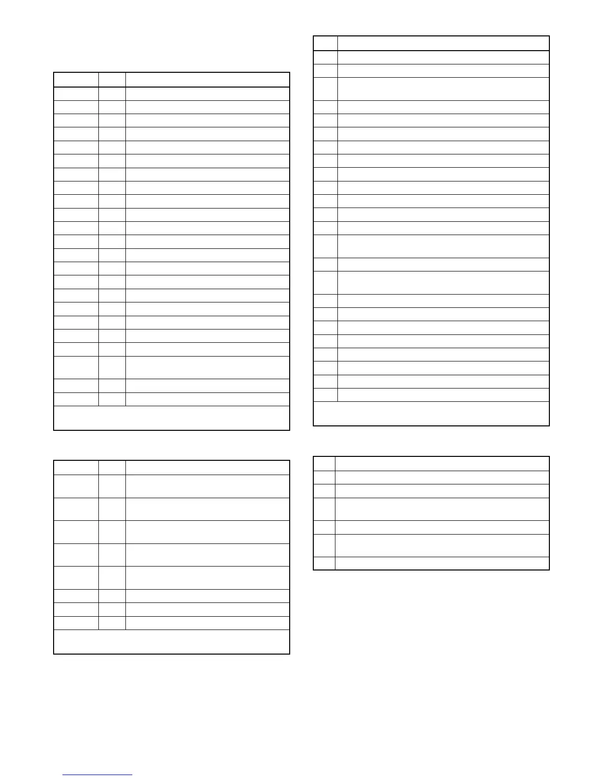
Terminal/Connector Identification
Terminal Wire Description
1 1A Emergency stop relay (K4) coil
2 1 Ground—emergency stop relay (K4)
3 42A Battery voltage (fuse #1 protected)
4 2 Ground
5 70C Generator in cool-down mode signal
6 70R Generator in running mode signal
7 56 Air damper indicator, if equipped
8 48 Emergency stop indicator
9 32A Common fault/prealarm
10 26 Auxiliary indicator
11 12 Overcrank indicator
12 39 Overspeed indicator
13 38 Low oil pressure indicator
14 36 High engine temperature indicator
15 60 System ready indicator
16 80 Not-in-auto indicator
17 41 Prealarm low oil pressure indicator
18 62 Low battery volts (active low*)
19 32 Common fault/prealarm
20 35 Low water temperature
21 40 Prealarm high engine temperature
indicator
22 63 Low fuel (active low*)
23 61 Battery charger fault (active low*)
* Check the operation of active low circuits by placing ground on
terminals so designated.
Figure 5 -3 Terminal Strip TB1
Terminal Wire Description
1 1P Prime power operation (requires
optional kit)
2 2P Prime power operation (requires
optional kit)
3 3P Prime power operation (requires
optional kit)
4 4P Prime power operation (requires
optional kit)
5 9 Crank mode (open-cyclic ground
continuous)
6 9A Crank mode ground
7 4 Remote start (active low*)
8 3 Remote start (ground)
* Check the operation of active low circuits by placing ground on
terminals so designated.
Figure 5 -4 Terminal Strip TB2
Pin Description
1 Output to K1 relay (crank relay), wire 71
2 Ground for speed sensor, wire 2
3 Output to safeguard breaker terminal, wire 70 (and
K5 relay if equipped with electronic governor)
4 Not used
5 Ground (--), wire N
6 Speed sensor shield ground, wire S2
7 Output to fuel solenoid (FS), wire 70
8 Battery positive to speed sensor, wire 24
9 Input from speed sensor, wire 16
10 Not used
11 Not used
12 Input from battery positive (14P)
13 Not used
14 Input from high exhaust temperature switch,
wire 31
15 Not used
16 Input from pre-high engine temperature switch, wire
40A
17 Input from aux. immediate shutdown
18 Not used
19 Not used
20 Not used
21 Input from high engine temperature switch, wire 34
22 Input from low oil pressure switch, wire 13
23 Input from pre-low oil pressure switch, wire 41A
24 Not used
* Check the operation of active low circuits by placing ground on
terminals so designated.
Figure 5 -5 P1 Connector Pins
Pin Description
1 Output to engine gauge, wire 70
2 Not used
3 Input for AC crank disconnect & instrumentation,
wire V7F
4 Not used
5 Input for AC crank disconnect & instrumentation,
wire V0
6 Engine ground, wire 2
Figure 5 -6 P2 Connector Pins
 Loading...
