TP-5737 5/0174 Section 7 Component Testing and Adjustment
TT-1123/347058-D
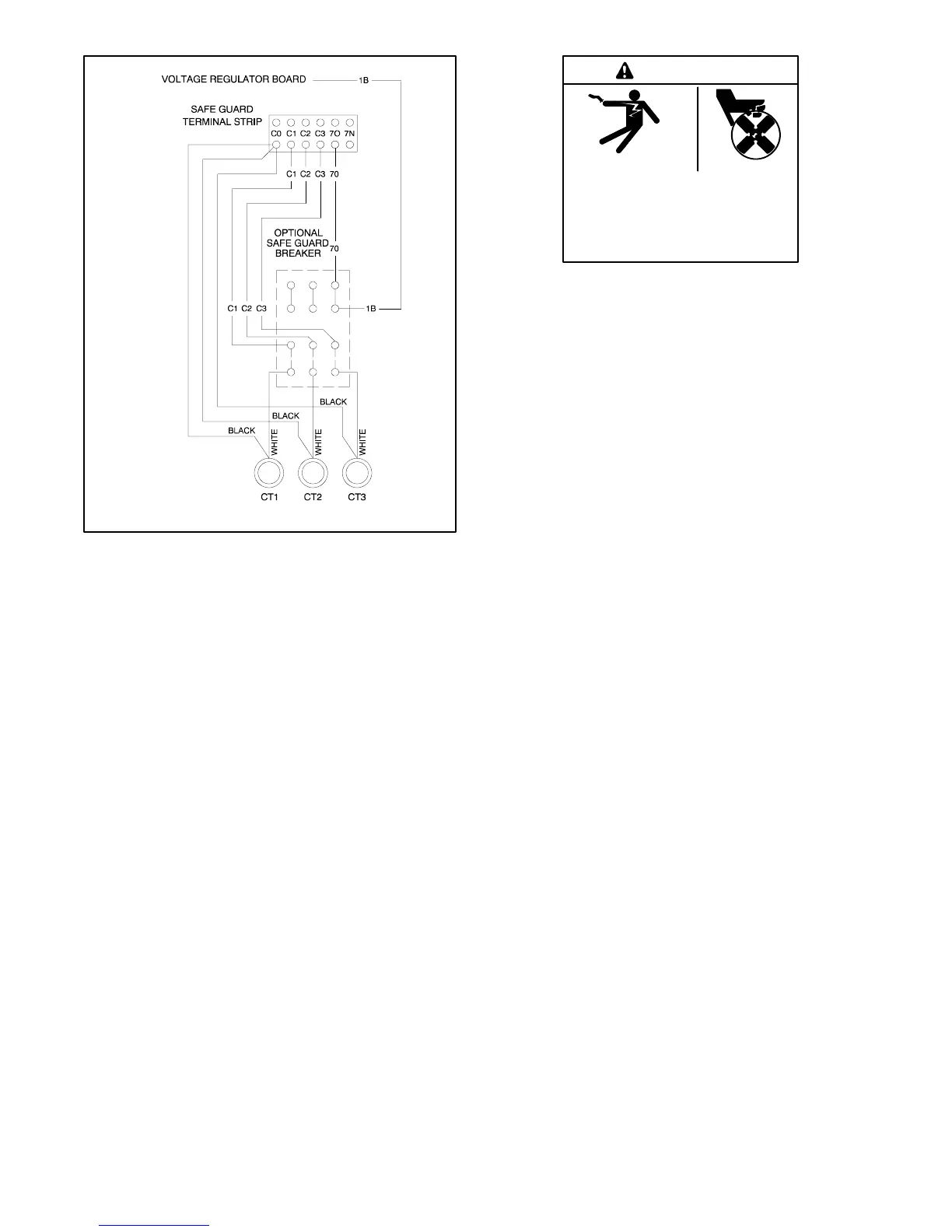
Figure 7 -20 Current Transformers
A current transformer contains a coil of wire that induces
a secondary voltage/current from the primary or stator
lead passing through the center. The number of coil
turns inside the current transformer determines the
ratio. Replacement current transformers must have the
same ratio as the original.
7.11.2 Testing
Use an ohmmeter to check the current transformer.
Perform this test with the current transformer
disconnected from the generator set. A resistance
reading of infinity or 0 ohms suggests an open or shorted
current transformer that needs replacement. Consider
any other resistance reading acceptable.
7.12 Reactive Droop Compensator
7.12.1 Function and Application
The reactive droop compensator kit distributes the
generator set load evenly between two generator sets in
parallel. If the kit is not factory installed, use the
installation instructions supplied with the kit for field
installation. Use the following procedure for reactive
droop compensator adjustment.
Hazardous voltage.
Can cause severe injury or death.
Operate the generator set only when
all guards and electrical enclosures
areinplace.
Moving rotor.
WARNING
Short circuits. Hazardous voltage/current can cause
severe injury or death. Short circuits can cause bodily injury
and/or equipment damage. Do not contact electrical
connections with tools or jewelry while making adjustments or
repairs. Remove all jewelry before servicing the equipment.
7.12.2 Reactive Droop Compensator
Adjustment Procedure
Parallel the two generator sets using the following
procedure. Read and understand the entire procedure
before beginning.
1. Remove any load connected to the generator set.
Start each generator set by placing the generator
set master switch in the RUN position.
2. Set the reactive droop compensator rheostat on
generator set no. 1 to the minimum
counterclockwise (CCW) setting. Record the RPM
or frequency and voltage at 1/4 load steps to full
load on unit no. 1
3. Repeat step 2 for generator set no. 2.
4. Compare the readings and make final adjustments
so that the voltage is within 1 volt at each load step
and the speed is within three RPM or the frequency
is within 0.1 Hz for each unit. Adjust the voltage
using the controller or remote voltage adjustment
potentiometer. Adjust the speed at the electronic
governor or at the remote adjusting potentiometer.
5. Check the droop compensation on each unit as
follows:
a. With unit no. 1 operating at the desired speed
and voltage, apply an inductive load one half to
full load. Do not use a resistive load for this test.
b. Observe the voltmeter on unit no. 1 with the
reactive droop compensator rheostat set at
minimum. As the rheostat is turned clockwise
(CW), the voltmeter should show a decrease in
voltage. If observing a larger voltage, stop the
 Loading...
