TP-5737 5/0164 Section 7 Component Testing and Adjustment
7.4 SCR Assembly and Photo
Transistor Board
7.4.1 Concept and Equipment
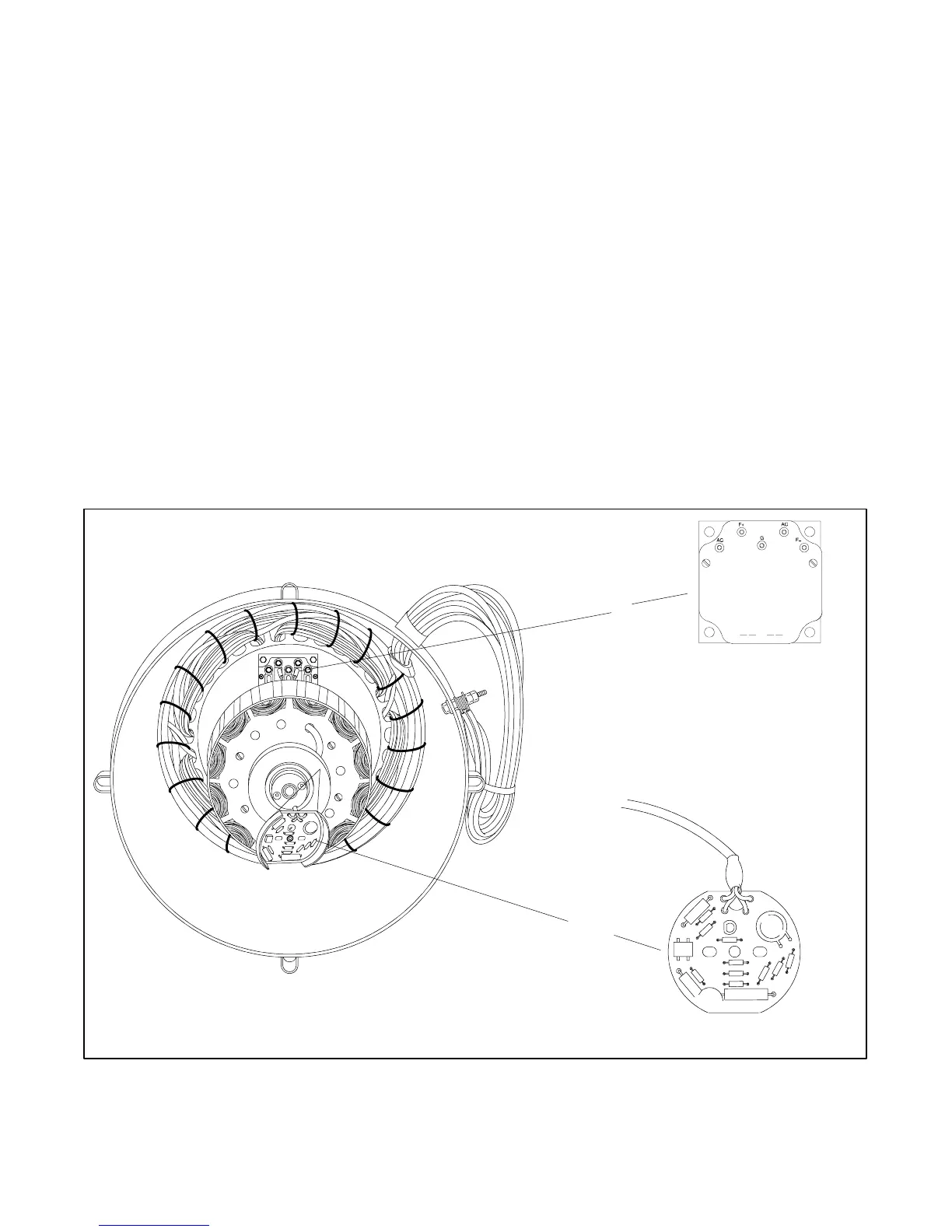
The SCR assembly mounts behind the exciter armature
and controls current flow to the generator field. The
command and sensing circuitry mounts on the
shaft-mounted photo transistor board. See Figure 7-8.
The generator set only functions if both components are
functional. The following test determines which
component is faulty. Because the end bracket must be
removed from the set to correctly test these
components, do not begin this procedure unless there is
reasonable certainty that these components are
inoperative. See Section 7.1, Generator
Troubleshooting. Examine the photo transistor board
for visible signs of damage (open foil patterns and heat
discoloration) before removing the entire SCR
assembly for testing. See Section 7.9, End Bracket
Removal and Replacement, and Section 8,
Disassembly/ Reassembly, for end bracket removal.
Testing the SCR assembly and photo transistor board
requires the following components:
D Light bulb with socket, one 120-volt/110-watt.
D Switch, double-pole/single-throw (DPST), 120-volt
10-amp minimum.
D Fuse, 1 amp, in holder.
D Plug with cord, 120-volt AC.
D SCR assembly and photo transistor board (one must
be functioning)
7.4.2 SCR Assembly and Photo
Transistor Board Test
This test simulates the normal operation of the
components when the generator is running. In the test,
a known working component (example: photo transistor
board) is matched with a component of unknown quality
(example: SCR assembly). If the components do not
function normally during the test, the component of
unknown quality may be inoperative. Test either
component in this manner.
3-100
R12758-8
B-292902
B-258545-A
2
1
1. SCR assembly 2. Photo transistor board
Figure 7 -8 Component Locations
 Loading...
