TP-5737 5/01 77Section 7 Component Testing and Adjustment
7.14 Governor Adjustment
7.14.1 Mechanical Governor
Note: Before checking and adjusting engine
speed, make sure the engine reaches its
normal operating temperature.
Note: All speed specs apply to an engine at
operating temperature under load
conditions. The maximum permissible
speed variation is 2--3 Hz or 50--90 rpm for
fast idle speed.
Mechanical Governor Adjustment Procedure
1. Disconnect the speed control from the fuel injection
pump lever and start the engine.
2. Verify that the injector pump lever holds in the fast
idle position against the fast idle adjusting screw.
See Figure 7-23.
3. Using a frequency meter, check the engine speed.
Adjust the engine speed at full load to 1800 rpm
(60 Hz) or 1500 rpm (50 Hz). To increase the
engine speed, turn the fast idle adjusting screw
counterclockwise; turn the fast idle adjusting screw
clockwise to decrease engine speed.
4. Reconnect the speed control to the fuel injection
pump lever.
5. Stop the generator set.
TP-5353-7
12
1. Injection pump lever
2. Fast idle adjusting screw
Figure 7 -23 Governor Adjustments, Typical
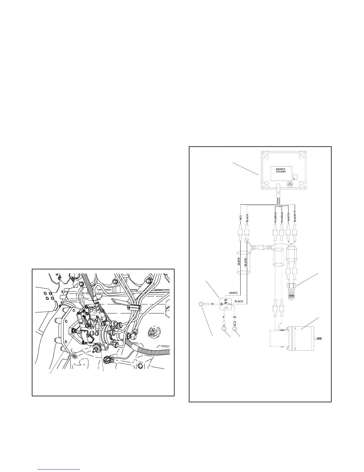
7.14.2 Electronic Governor—Barber-
Colman Dyna 2500 125--150 kW
John Deere Engine-Powered 6081
Some sets are equipped with Barber-Colman Dyna
2500 electronic governors. Because this is an
electronic device, no mechanical drive or hydraulic
connection is required. The system consists of a
magnetic pickup, an electronic control unit, and an
actuator. The magnetic pickup monitors engine speed
and transmits this information to the electronic control
unit (see Figure 7-24 or Figure 7-25). The electronic
control unit interprets the signal from the magnetic
pickup to control current input to the throttle actuator.
The throttle actuator adjusts the throttle position on the
engine. See Figure 7-26.
KC250000B-A
1
2
3
456
7
1. Control unit
2. Magnetic pickup
3. Actuator
4. Connect to safeguard breaker terminal strip
5. Connect to cranking solenoid, battery (+)
6. Connect to 70 on safeguard breaker terminal block
7. Relay
Figure 7 -24 Governor Control Unit,
Nonparalleling Generator Set
 Loading...
