TP-5737 5/01 73Section 7 Component Testing and Adjustment
7.10 Speed Sensor Test
The following procedure determines if the speed sensor
(overspeed fault) is emitting a signal.
Speed Sensor Signal Test
1. With the generator set master switch in the
OFF/RESET position, connect a DC voltmeter
between the positive (+) lead (wire 24) at the speed
sensor and the ground (wire 2). The voltmeter
should indicate approximately 8--10 volts DC.
2. With the generator set running, connect the DC
voltmeter negative probe to the 0 terminal (wire
16—white) on the speed sensor. Place the
voltmeter positive probe on the positive (+) terminal
(wire 24—red). The voltmeter should indicate
approximately 12 volts DC.
Note: During the test the controller leads must
remain connected to the speed sensor
terminals. Slide the leads from the speed
sensor terminals only enough to expose the
connection for the test leads. Do not
disconnect the leads.
If the speed sensor emits a signal, check the continuity
of the speed sensor leads (wires 2, 16, and 24) between
the controller P1 connector and the lead terminals at the
speed sensor.
If the speed sensor does not emit a signal, test the speed
sensor through the following procedure.
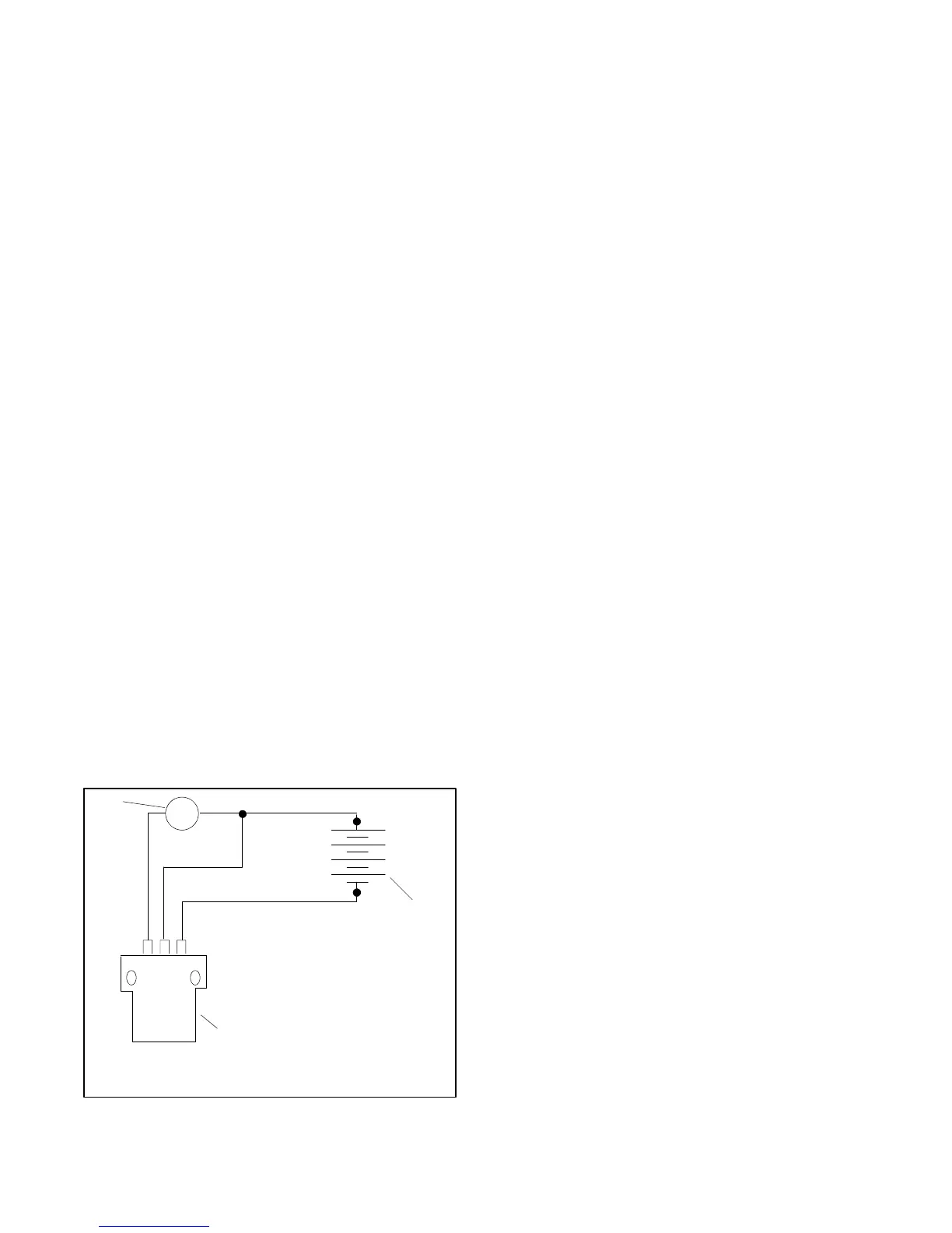
Speed Sensor Test
1. Connect the speed sensor, voltmeter, and DC
voltage source as shown in Figure 7-19.
o + ---
+
---
+
1
2
3
TP-5353-7
1. DC voltmeter
2. 12-volt battery or DC power supply
3. Speed sensor
Figure 7 -19 Speed Sensor Test
2. Touch the sensing surface with a flat piece of iron or
steel at least 4.1 cm (1/4 cubic inch) in size. The
voltmeter test reading should equal the source
voltage.
3. Remove the iron or steel from the sensing surface.
Observe no test voltmeter reading.
7.11 Current Transformers
7.11.1 Function and Application
Current transformers provide several generator set
functions including signal/drive for:
D Controller AC voltmeter/ammeter
D Safeguard circuit breaker
D Reactive droop compensator.
Generator set models do not have current transformers
when they do not include the above items. The meters
and safeguard circuit breaker share the same current
transformer while the reactive droop compensator uses
a separate current transformer. See Figure 7-20. The
generator set junction box contains the stator leads and
the current transformers.
When replacing the current transformer or stator
assembly, install the current transformer according to
the generator reconnection decal on the generator set,
or see Section 9, Wiring Diagrams. Observe the correct
current transformer position when installing the stator
leads. The current transformer dot or HI mark position
and the stator lead direction are essential for correct
component function.
 Loading...
