TP-5737 5/0168 Section 7 Component Testing and Adjustment
7.6 Stator
Note: When replacing the rotor or stator, use a
skewed (slanted) rotor with a straight stator
per original manufacturer.
Stator Test Procedure
1. Check the generator output leads for proper
connections. See Section 9, Wiring Diagrams.
2. Check the stator windings for:
a. Shorted windings: Replace the stator if burnt or
hot windings exist. See Figure 7-12.
Note: Disconnect V7, V8, V9, and V0 leads at
the controller AC fuse terminal blocks
before performing the open winding test.
b. Open windings: With an ohmmeter, check each
pair of leads for low resistance readings
(continuity). High resistance across A or low
resistance (continuity) across B and ground
indicates a faulty stator; if so, replace the stator.
See Figure 7-13.
3-100
R12758-8
2
1
1. Leads
2. Windings
Figure 7 -12 Stator
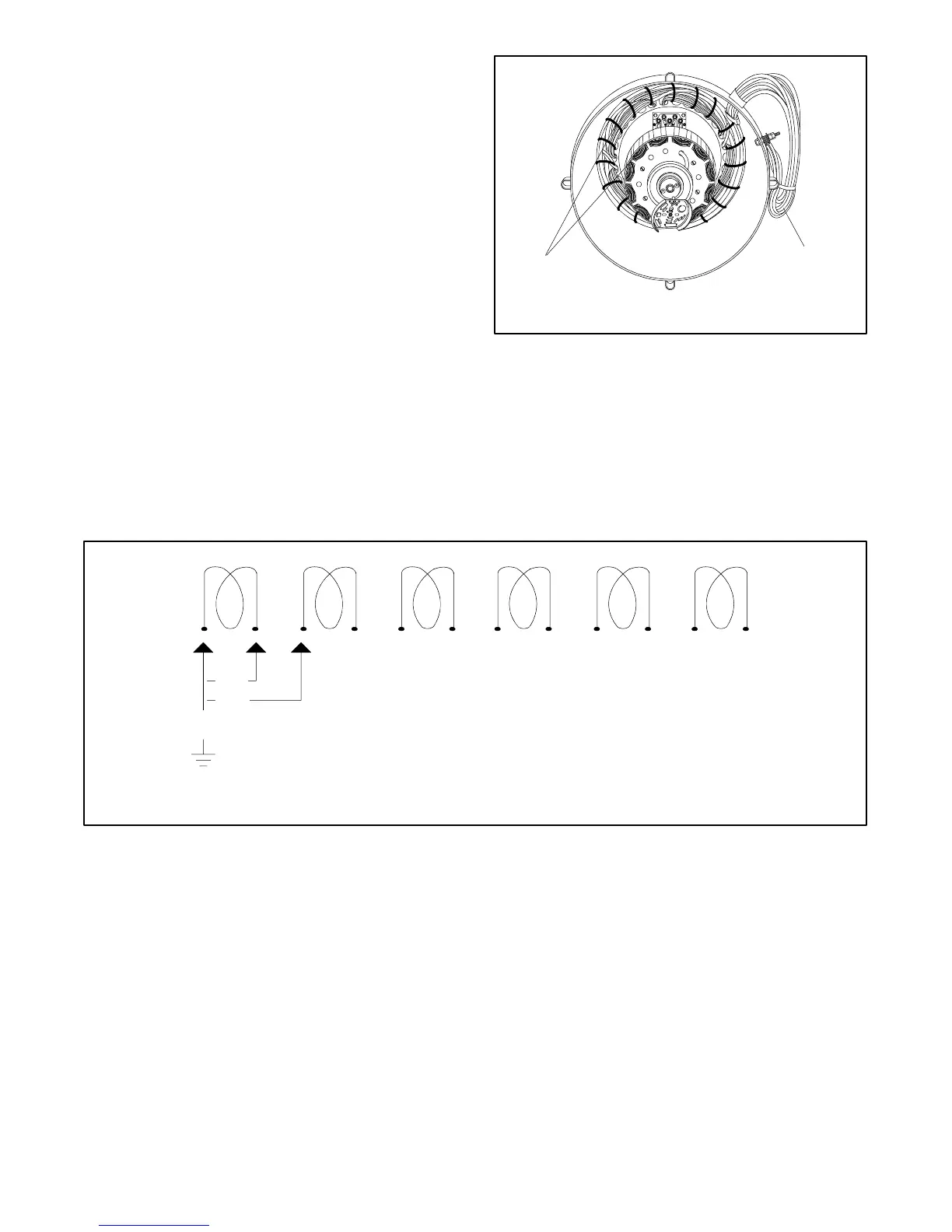
A
B
C
142536710811912
TP-5353-7
A. Continuity/resistance
B. No continuity
C. No continuity
Figure 7 -13 Stator Winding Test
 Loading...
