TP-5737 5/0142 Section 5 Decision-Makert 3+ Troubleshooting
5.4.6 Generator Condition Indicator
Terminal (TB1 Terminal Strip)
Remote accessories (audiovisual alarm, remote
annunciator, dry contact kits, etc.) may be connected to
the controller TB1 terminal strip to signal the condition of
the generator set. Some generator sets may not be
equipped with the optional sending devices necessary
to operate all generator condition indicators. If the
remote accessories do not operate, test for output
voltage at the TB1 terminal strip. To test the operation of
each indicator, move the generator set master switch
and FASTCHECK
â
toggle in the position prescribed.
Test point voltage is slightly less than the voltage being
supplied to the controller (12 or 24 volts). If correct
voltage is not detected at the test point, remote
accessories (audiovisual alarm, remote annunciator,
dry contact kits, etc.) do not function. Test point
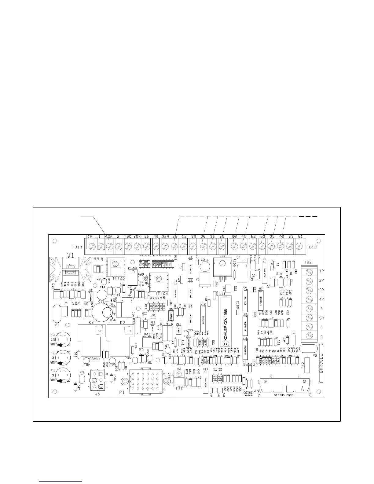
connections are shown in Figure 5-29 and Figure 5-30.
Note: When checking controller test point voltage,
place the negative (--) lead of the voltmeter on the
terminal designated in Figure 5-30 and the
voltmeter positive (+) lead on TB1-42A.
Note: Because of the absence of AC output, the
auxiliary lamp flashes during the controller
testing on 16-light microprocessor controllers.
The NOT-IN-AUTO lamp illuminates whenever
the generator set master switch is not in the
AUTO position on 16-light microprocessor
controllers.
Note: Leave the FASTCHECK
â
engine switch in the
RUN position for at least 30 seconds before
pushing the toggle switches. Toggle the
generator set master switch to the OFF/RESET
position. Move the FASTCHECK
â
engine switch
to the OFF position. Move the generator set
master switch to the RUN position. Observe IGN,
CRK, and REG lamps light. Within 5 seconds,
move the FASTCHECK
â
engine switch to the
RUN position.
A-336415-L
1
2
1. TB1-42A 2. TB1—(see chart titled generator condition indicator terminals)
Figure 5 -29 Indicator Lamp Test Connections
 Loading...
