TP-5737 5/0134 Section 5 Decision-Makert 3+ Troubleshooting
5.3.2 Fuses
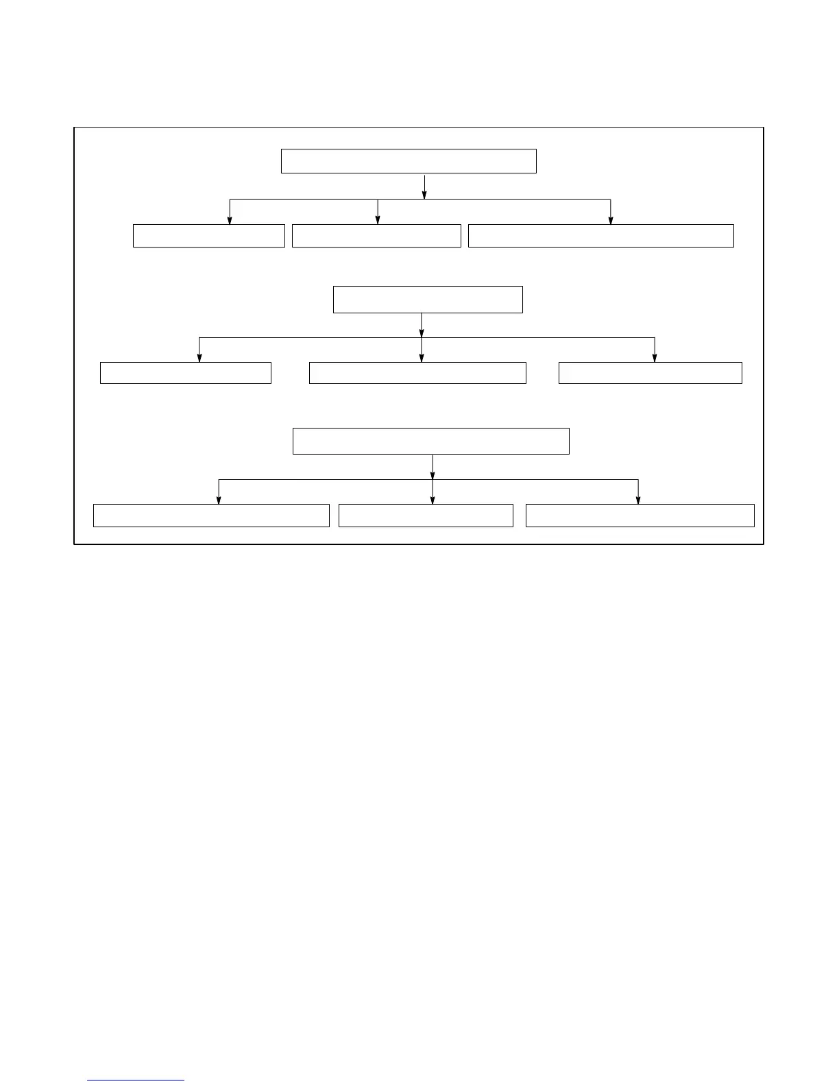
The following chart lists the possible causes of blown
controller fuses F1, F2, and F3. If a fuse blows, replace it
and resume operation. If the fuse blows again, use
Figure 5-17 to identify the faulty component(s).
Inoperative audio/visual alarm
Blown F1 fuse (remote annunciator: 3 amp)
Blown F2 fuse (controller: 3 amp)
Battery connections reversed Shorted DC supply to indicator panel Shorted controller circuit board
Blown F3 fuse (engine and accessories: 15 amp)
Inoperative engine electrical components Inoperative overvoltage board Inoperative panel lamps, engine gauges
Inoperative dry contact kit Remaining accessories connected to TB1-42A
Figure 5 -17 Checking F1, F2, and F3 Fuses
 Loading...
