4.3
Section 4
Air Cleaner and Air Intake System
4
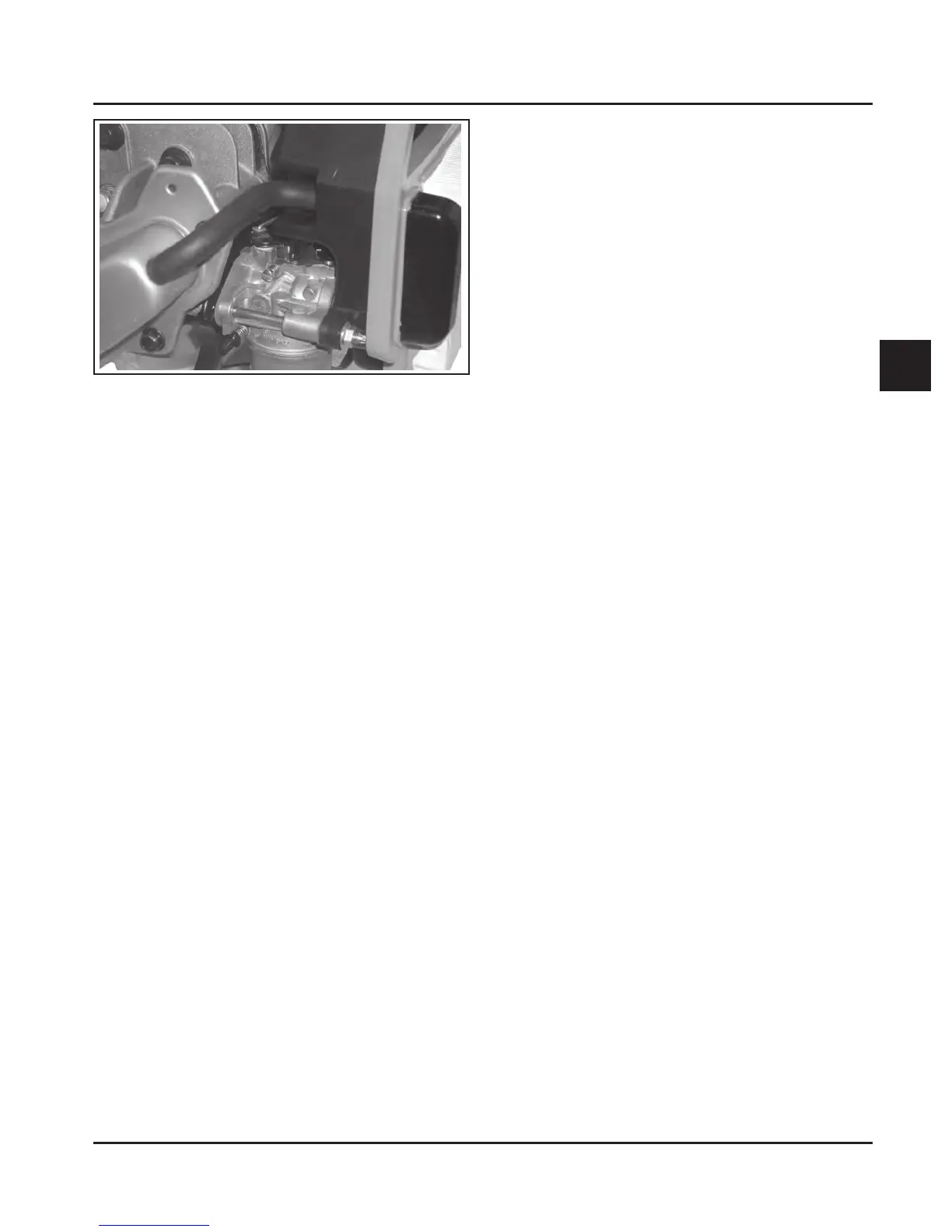
Figure 4-3. Breather Hose.
Disassembly
The following procedure is for complete disassembly
of all air cleaner components. As the removal of the air
cleaner base also affects carburetor mounting and
governor adjustment, steps 3 and 4 should only be
performed if required. Detailed photos are provided in
Sections 5, 8, and 10 for the various individual steps.
1. Loosen the air cleaner cover retaining knobs and
remove the air cleaner cover.
2. Remove the foam precleaner (if so equipped),
and the air cleaner element with formed rubber
seal.
3. Disconnect the breather hose from the valve
cover or air cleaner base.
NOTE: The air cleaner base should be removed
only if necessary.
4. Remove the two hex. flange nuts from the
mounting studs. If one stud and one thread
forming screw is used; first remove the thread
forming screw on the right side of the carburetor
inlet, which secures the air cleaner base,
carburetor and gaskets. Insert a 3/16” diameter
rod approximately 4” long, into the hole to serve
as a temporary alignment pin. Be careful not to
force the rod or damage the threads. Then
remove the hex. flange nut from the stud on the
left side of the carburetor inlet. Carefully remove
the air cleaner base and gasket. The cover
mounting studs thread into the air cleaner base,
and they should only be removed if necessary.
Reassembly
The following procedure is for complete assembly of
all air cleaner components. Steps 1-3 are necessary
only if the air cleaner base and/or the cover mounting
studs were removed in “Disassembly”.
1. Install the mounting studs into the air cleaner
base if removed previously. Tighten the studs until
bottomed, or to the end of threads (do not force).
2. Install the air cleaner base gasket and air cleaner
base, with the two metal spacers, onto the
mounting stud(s) and/or alignment pin. Make sure
the upper mounting tab is located above the
closure plate. Install and finger tighten the hex.
flange nut(s). When a long M6 thread forming
mounting screw is used, apply hand pressure to
keep the parts from shifting, then remove the
alignment pin and install the M6 thread forming
screw. DO NOT OIL. Torque the nut(s) to 5.5 N·m
(48 in. lb.). Torque the screw to 8.0 N·m
(70 in. lb.) into a new hole, or 5.5 N·m (48 in. lb.)
into a used hole, do not over tighten.
3. Reconnect the breather hose and perform the
governor adjustment (See Section 5, “Initial
Governor Adjustment”).
4. Install the air cleaner element with the pleated
side “out” and seat the rubber seal onto the edges
of the air cleaner base.
5. Install the serviced precleaner (if so equipped)
into the air cleaner cover. Make sure the hole in
the precleaner is aligned with the upper mounting
knob.
6. Reinstall the air cleaner cover and secure with the
two knobs.
Not For Resale
www.SmallEngineDiscount.com

 Loading...