10.9
Section 10
Reassembly
10
Figure 10-32. Assembling Cylinder Head.
Install Cylinder Head
NOTE: Do not reuse cylinder head screws or
gasket, always replace with new parts.
1. Check to make sure there are no nicks or burrs
on the sealing surfaces of the cylinder head or
crankcase.
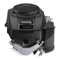
Figure 10-29. Aligning and Installing Closure Plate.
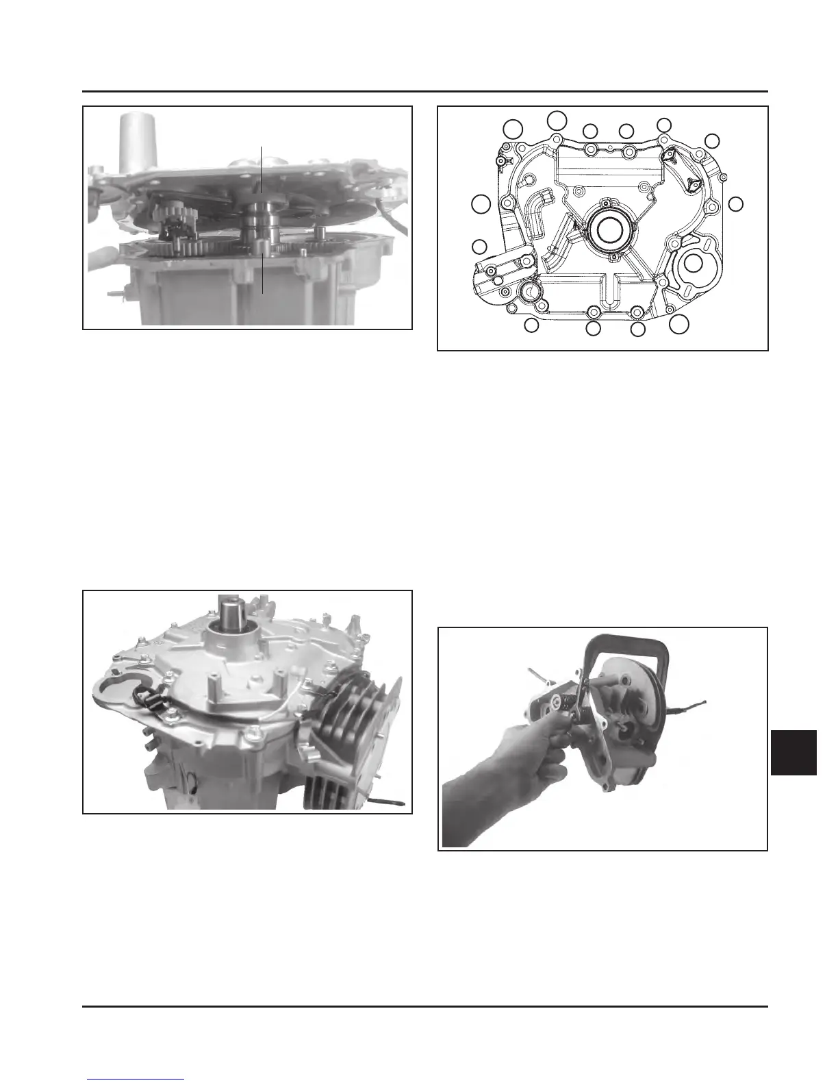
4. Install the fourteen hex. flange screws securing
the closure plate to the crankcase, with any
clamps for the wiring harness and the sheathed
RFI suppression spark plug lead (#5 location, if
so equipped), positioned as shown in Figure
10-30. If the wiring harness was separated from
the closure plate, route the harness through the
clamps and the slot in the closure plate. Close
the clamps to retain the harness.
5. Torque the closure plate fasteners to 24.5 N·m
(216 in. lb.) using the sequence shown in Figure
10-31.
Figure 10-30. Closure Plate Installed.
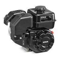
Figure 10-31. Closure Plate Fastener Torque
Sequence.
Assemble Cylinder Head
Prior to assembly, lubricate all the components with
engine oil, including the tips of the valve stems and
valve guides. Using a valve spring compressor, install
the following items in the order listed. See Figure
10-32.
• Intake and exhaust valves
• Valve spring caps
• Valve springs
• Valve spring retainers
• Valve spring keepers
5
1
3
7
10
8
9
12
4
2
6
11
Guide Channel
Guide Shoe
14
13
Not For Resale
www.SmallEngineDiscount.com

 Loading...