10.6
Section 10
Reassembly
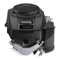
Figure 10-17. Direction Arrow on Piston.
Install Cam Levers
1. Install the two cam levers as shown in Figure
10-20. The “dimple” for seating the push rod
must face “up”. Secure each cam lever using an
M6 hex. flange screw. Torque the screws to
7.5 N·m (65 in. lb.). Lubricate the dimple and
bottom side of the cam lever with light grease or
oil.
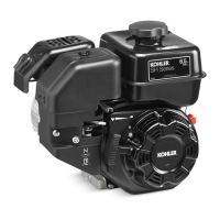
Figure 10-18. Installing Piston and Connecting
Rod.
3. Guide the connecting rod down and rotate the
crankshaft to mate the journals. Install the rod
cap.
4. Install the hex. flange screws and torque in 2
increments, first to 5.5 N·m (50 in. lb.), finally to
11.5 N·m (100 in. lb.). See Figure 10-19.
Figure 10-20. Installing Cam Levers.
Install the Exhaust Cam Shaft and Cam
Gear
1. If the drive pins were removed from the exhaust
cam shaft, follow the same procedure used earlier
for the intake cam shaft and reinstall them. See
Figure 10-21.
Figure 10-19. Torquing Connecting Rod Fasteners.
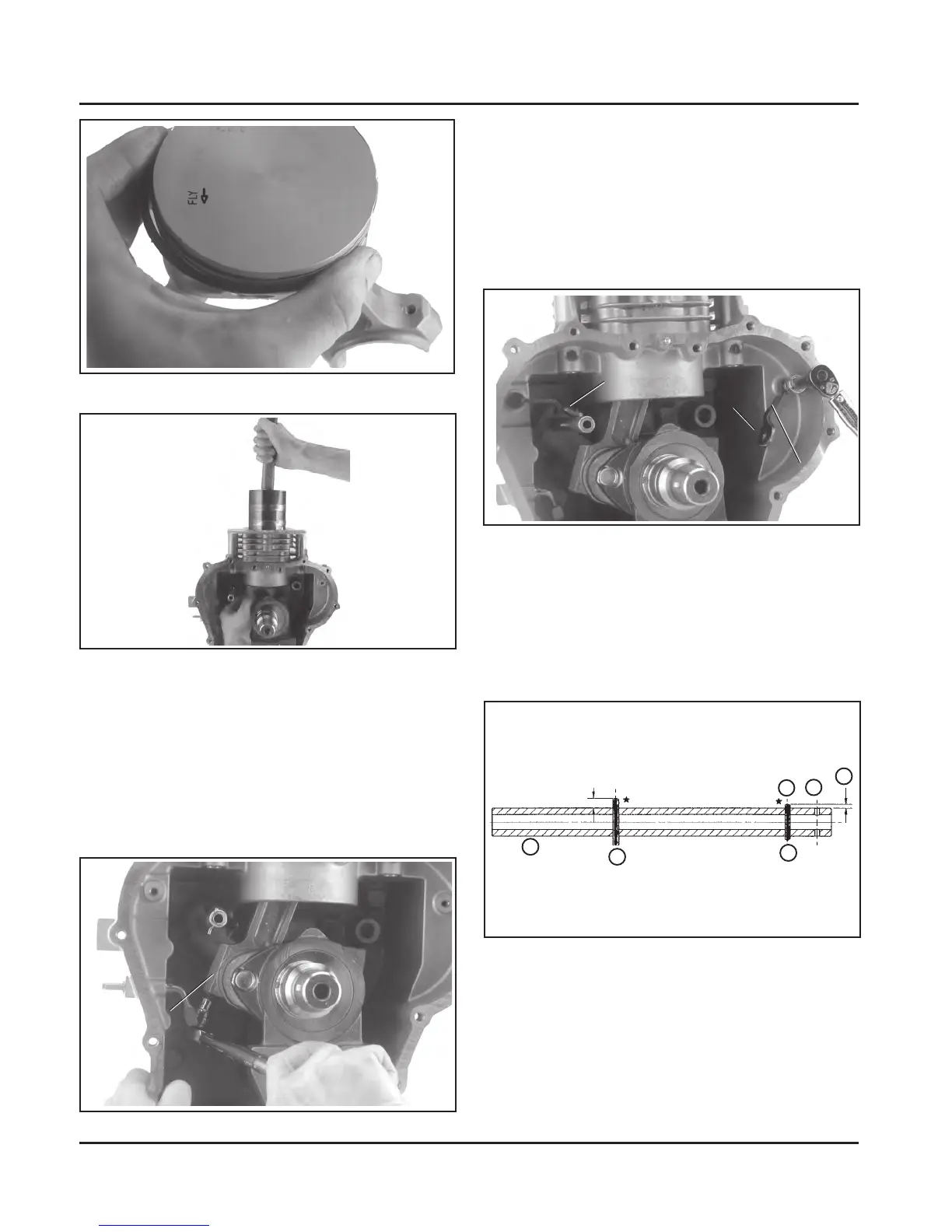
Figure 10-21. Drive Pin Locations for Exhaust Cam
Shaft.
1. Exhaust Cam Shaft
2. 3 mm Diameter Pin
3. 2.5 mm Diameter Pin
4. 1.86 mm
5. #1 Hole Location
6. #2 Hole Location
5
1
4
3
2
6
Connecting
Rod Cap
Intake Cam
Follower
Dimple
Exhaust
Cam
Follower
Not For Resale
www.SmallEngineDiscount.com

 Loading...