5.14
Section 5
Fuel System and Governor
Operation
As the governor gear rotates, centrifugal force causes
the flyweights to move outward as speed increases. As
the flyweights move outward, they cause the regulating
pin to move outward.
The regulating pin contacts the tab on the cross shaft,
causing the shaft to rotate. One end of the cross shaft
protrudes through the side of the crankcase. The
governor lever is clamped on the protruding end of the
shaft and connected with linkage to the throttle lever
on the carburetor, so any rotation of the shaft causes
corresponding movement of the throttle plate.
When the engine is at rest, and the throttle is in the
‘‘fast’’ position, the tension of the governor spring holds
the throttle plate open. When the engine is operating
(the governor gear assembly is rotating), the force
applied by the regulating pin against the cross shaft
tends to close the throttle plate. The governor spring
tension and the force applied by the regulating pin are
in ‘‘equilibrium‘‘ during operation, holding the engine
speed constant.
When load is applied and the engine speed (and
governor gear speed) decreases, the governor spring
tension moves the governor arm to open the throttle
plate wider. This allows more fuel into the engine;
increasing engine speed. This action takes place very
rapidly, so a reduction in speed is hardly noticed. As
the speed reaches the governed setting, the governor
spring tension and the force applied by the regulating
pin will again be in equilibrium. This maintains the
engine speed at a relatively constant level.
The governed speed setting is determined by the
position of the throttle control. It can be variable or
constant, depending on the application.
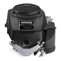
Initial Adjustment
Make this initial adjustment whenever the governor
arm is loosened or removed from the cross shaft. To
ensure proper setting, make sure the throttle linkage is
connected to the governor arm and the throttle lever
on the carburetor. See Figures 5-21 and 5-22.
1. Move the governor lever toward the carburetor
(wide open throttle). Do not apply excess force
flexing or distorting the throttle link.
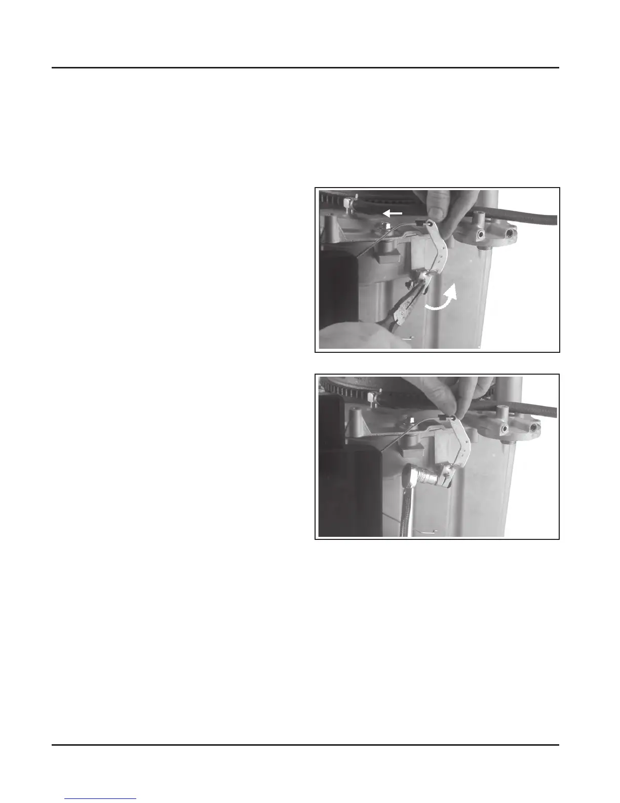
2. Grasp the cross shaft with pliers, and turn the
shaft counterclockwise as far as it will go, then
tighten the hex. nut. Torque the hex. nut to
7.0-8.5 N·m (60-75 in. lb.).
Figure 5-21. Governor Adjustment.
Figure 5-22. Tightening Governor Lever Nut.
Not For Resale
www.SmallEngineDiscount.com

 Loading...