Product description
Function description
4 Fuel filter 5.4 B704 and B705 – HP pump
(Bank A and B)
10 Distribution Block
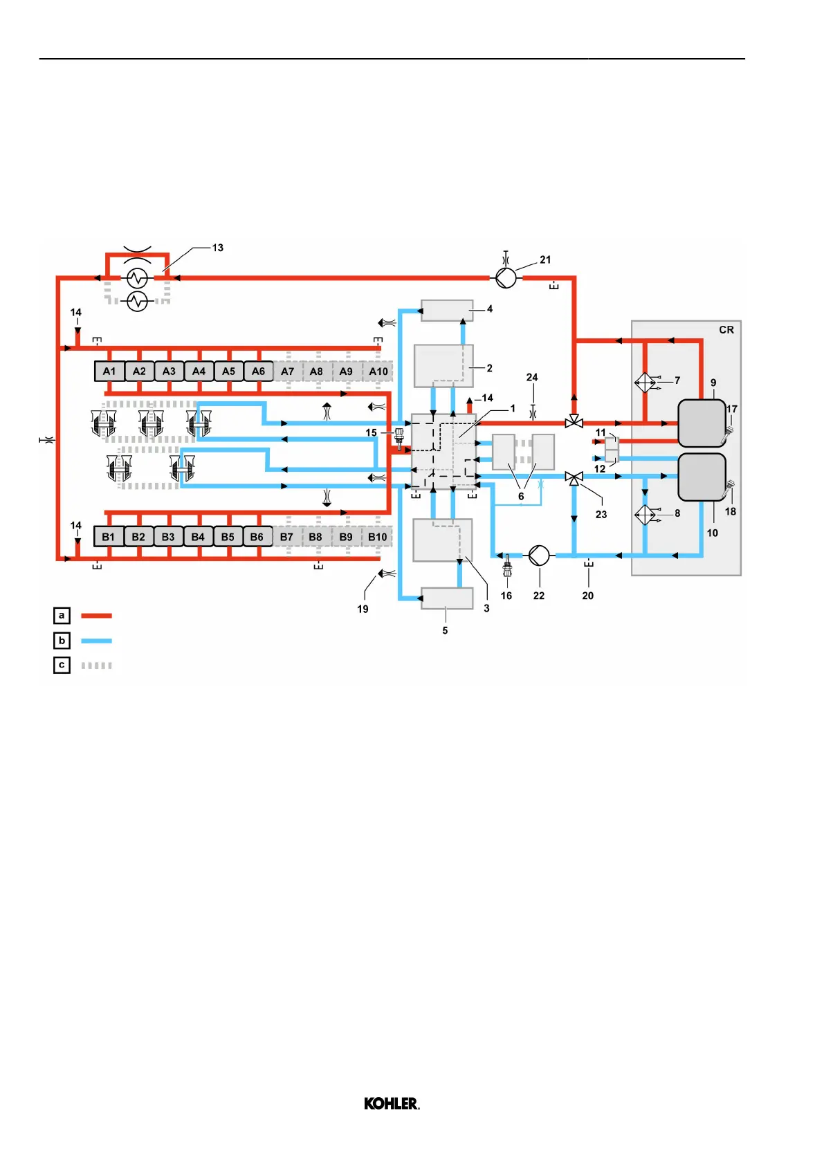
1.2.2 Cooling system
Coolant diagram
Fig. 21: Coolant diagram
a
High temperature c Depending on engine config‐
uration
b Low temperature CR Customer responsibility
1 Aggregate support 8 LT Water radiator 19 Venting point
2 Charge Air Cooler A 9 HT Expansion tank (including
ventilation line)
20 Drain point
3 Charge Air Cooler B 10 LT Expansion tank (including
ventilation line)
21 Coolant pump HT
4 Elbow A 11 Venting HT 22 Coolant pump LT
5 Elbow B 12 Venting LT 23 Mechanical thermostat
6 ECU 2-HD 13 Engine oil cooler 24 Manual venting point
7 HT Water radiator 14 Preheating
Sensors list
15 B708 – Coolant temperature
after engine
17 S710 – HT Coolant Min level
alert
16 B718 – Coolant temperature
before cooler
18 S711 – LT Coolant Min level
alert
30
© 2022 by Kohler Co. All rights reserved.
KD62V12 33525088601_8_1 EN_US
2022-09
 Loading...