82E-5 – 98E-5 SERIES 11-7
11. ELECTRIC WIRING
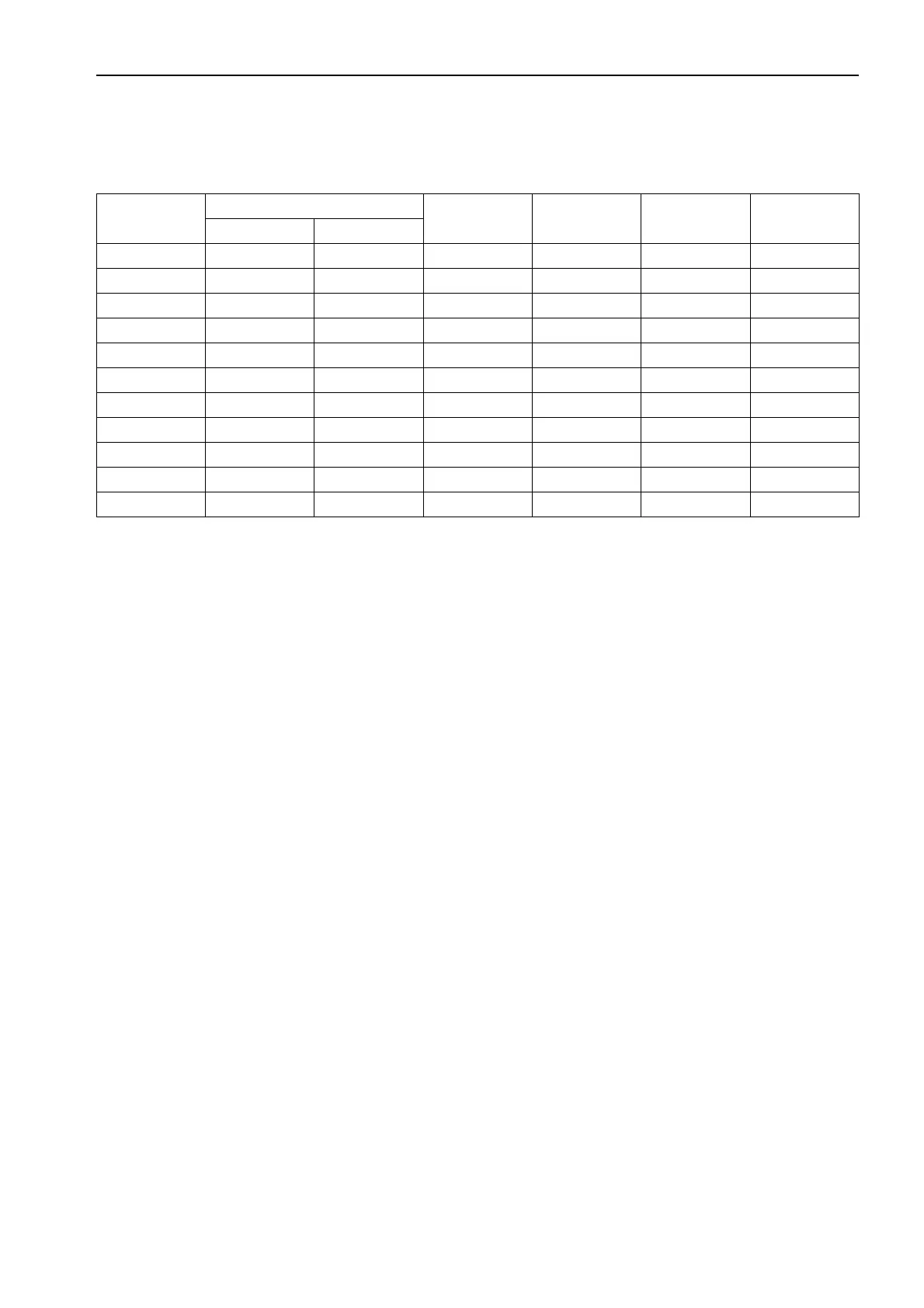
11.2.4 Section area and resistance of electric wire
(1) Allowable maximum cable length (Terminal resistance is not included.)
Note1) Allowable maximum resistance of Battery cable
Note2) Allowable maximum resistance of Starting motor circuit
(2) Terminal resistance
Generally, a terminal resistance is 15 m
z per coupler and 0 z per screw setting. This resistance should be
included in allowable maximum resistance when the cable length is planned.
Cable size
(mm
2
)
Cable construction
Resistance
(
z/m)
2 m
z
Note1
(m)
20 m
z
Ref.
(m)
50 m
z
Note2
(m)
Element No. Cable dia.
3 41 ø0.32 0.005590 0.36 3.58 8.94
5 65 ø0.32 0.003520 0.57 5.68 14.20
8 50 ø0.45 0.002320 0.86 8.62 21.55
15 84 ø0.45 0.001380 1.45 14.49 36.23
20 41 ø0.80 0.000887 2.25 22.55 56.37
30 70 ø0.80 0.000520 3.85 38.46 96.15
40 85 ø0.80 0.000428 4.67 46.73 116.82
50 108 ø0.80 0.000337 5.93 59.35 148.37
60 127 ø0.80 0.000287 6.97 69.69 174.22
85 169 ø0.80 0.000215 9.30 93.02 232.56
100 217 ø0.80 0.000168 11.90 119.05 297.62

 Loading...
