4-26 82E-5 – 98E-5 SERIES
4. DISASSEMBLY, INSPECTION AND REASSEMBLY OF ENGINES
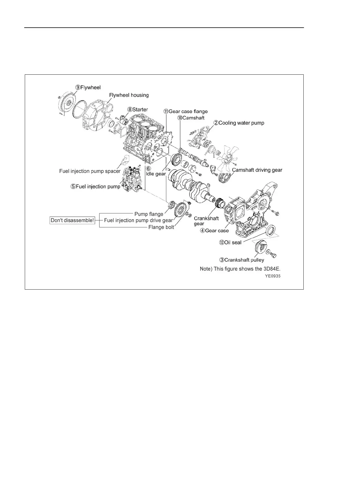
4.3 Gear Train and Camshaft
4.3.1 Components
4.3.2 Disassembly procedure
Disassemble in the order of the numbers in the illustration.
1) Perform steps 1) to 12) of the cylinder head disassembly procedure.
2) Remove the cooling water pump.
3) Remove the crankshaft pulley. (See Point 1 of 4.3.4)
4) Remove the gear case cover. (See Point 2 of 4.3.4)
5) Remove the fuel injection pump. (See Point 3 of 4.3.4)
6) Remove the idle gear ass’y. (See Point 4 of 4.3.4)
7) Remove the PTO drive gear. (See Point 5 of 4.3.4)
8) Remove the starting motor.
9) Remove the flywheel. (See Point 6 of 4.3.4)
10) Remove the camshaft ass’y. (See Point 7 of 4.3.4)
11) Remove the gear case. (See Point 8 of 4.3.4)
12) Remove the oil seal from the gear case cover. (See 4.3.6)
4.3.3 Reassembly procedure
Reverse of the disassembly procedure.

 Loading...
