OPERATION EXPLANATION OF COMPONENTS
3-37
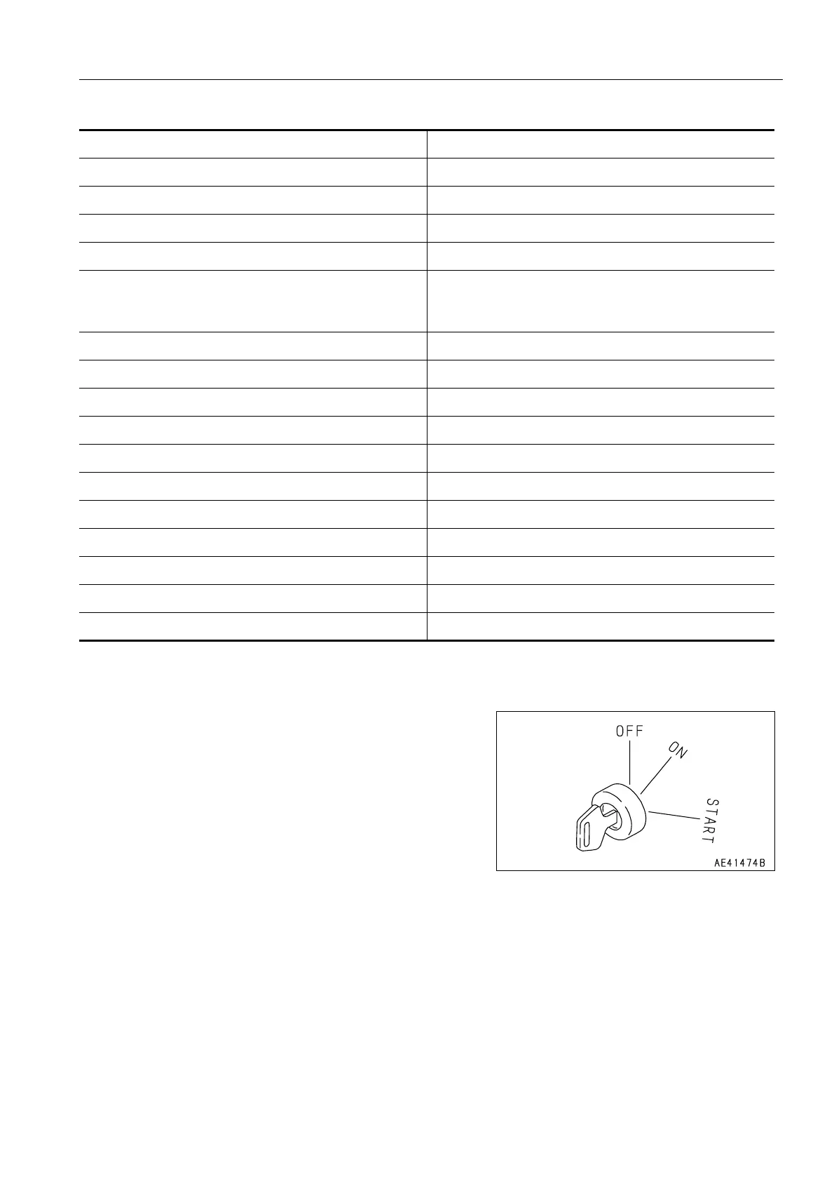
STARTING SWITCH 0.
This switch(1) is used to start or stop the engine.
OFF position
It is possible to insert and remove the starting switch key, all
the electric system switches are turned off, and the engine
stops. In addition, the parking brake is automatically applied.
ON position
Electric current flows in the charging circuit, lamp circuit, and
accessory circuit.
Keep the starting switch key at the ON position while the
engine is running.
START position
This is the position to start the engine. Hold the key at this position while cranking. Release the key immediately
after the engine has been started. The key will return to the ON position when released.
(1) Starting switch (17) Rear wiper switch
(2) Power mode selector switch (18) Cigarette lighter
(3) Transmission shift mode selector switch (19) Room lamp switch
(4) Transmission cut-off switch (20) Rear heated wire glass switch
(5) Transmission cut-off set switch (21) E.C.S.S. switch
(6) Lamp switch
(6) Turn signal lever
(6) Dimmer switch
(22) Emergency steering switch
(7) Horn switch (23) Cooling fan reverse rotation switch
(8) Hazard lamp switch (24) Directional selector switch (option)
(9) Parking brake switch (25) Directional selector actuation switch (option)
(10) Front working lamp switch (26) Semi auto digging switch (option)
(11) Rear working lamp switch (27) Remote positioner raise mode switch (option)
(12) Monitor panel mode selector switch 1 (28) Remote positioner lowet mode switch (option)
(13) Monitor panel mode selector switch 2 (29) Remote positioner raise/lower set switch (option)
(14) Kickdown switch (30) Aftercooler tilt switch (option)
(15) Hold switch (31) Torque converter lock-up switch (option)
(16) Front wiper switch (32) Load meter cancel switch (option)
(33) Load meter subtotal switch (option)

 Loading...