2PX/2PY
2-2-1
2-2 Electrical Parts Layout
2-2-1 Electrical parts layout
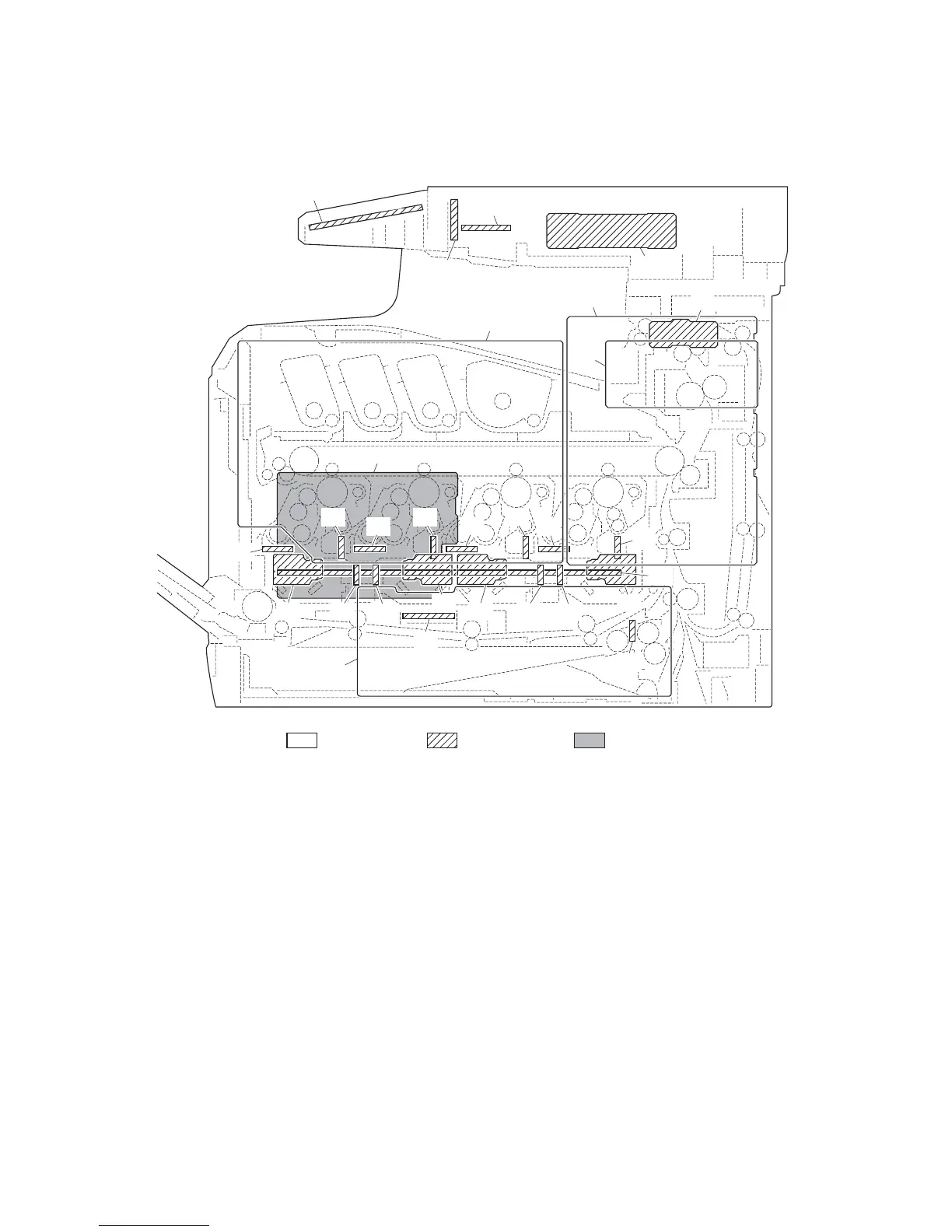
(1) PWBs
Figure 2-2-1 PWBs
1. Main PWB (MPWB) .............................. Controls the software such as the print data processing and
provides the interface with computers.
2. Engine PWB (EPWB)............................ Controls printer hardware such as high voltage/bias output con-
trol, paper conveying system control, and fuser temperature con-
trol, etc.
3. Power source PWB (PSPWB) .............. After full-wave rectification of AC power source input, switching
for converting to 24 V DC and 5V DC for output. Controls the
fuser heater.
4. High voltage PWB (HVPWB) ................ Generates main charging, developing bias, transfer bias and
cleaning bias.
5. Operation panel PWB (OPPWB) .......... Controls the touch panel. Consists the touch panel, LED indica-
tors and key switches.
6. Relay PWB (RPWB) ............................. Consists of wiring relay circuit between main PWB and engine
PWB and power source PWB.
7. Drum relay PWB (DRRPWB)................ Consists of wiring relay circuit between engine PWB and the
drum units and developing units.
1
3
13
16
2
4
28
17
21
25 24
20
19
9
6
23 22
18
7
15
8
26
29
14
12 11
10
27
Machine insideMachine right Machine left
5, 30-33
 Loading...