Page 21
S10 automatically closes when heat exchanger tem
peratures drop below limit setting. If there is a heat
ing demand, ignition control A3 cycles through a nor
mal ignition timing sequence. Do not change factory
limit setting. S10 is set to limit maximum discharge
air temperature. This is a safety shut down function.
220°
F
LIMIT CONTROL S10 V" MODELS
GSR21V580
UNIT
LIMIT SETTING
TABLE 7
GSR21V5−100
G21V360
G21V380
G21V580
180°
F
G21V5100
GSR21V380
200°
F
170°
F
170°
F
160°
F
180°
F
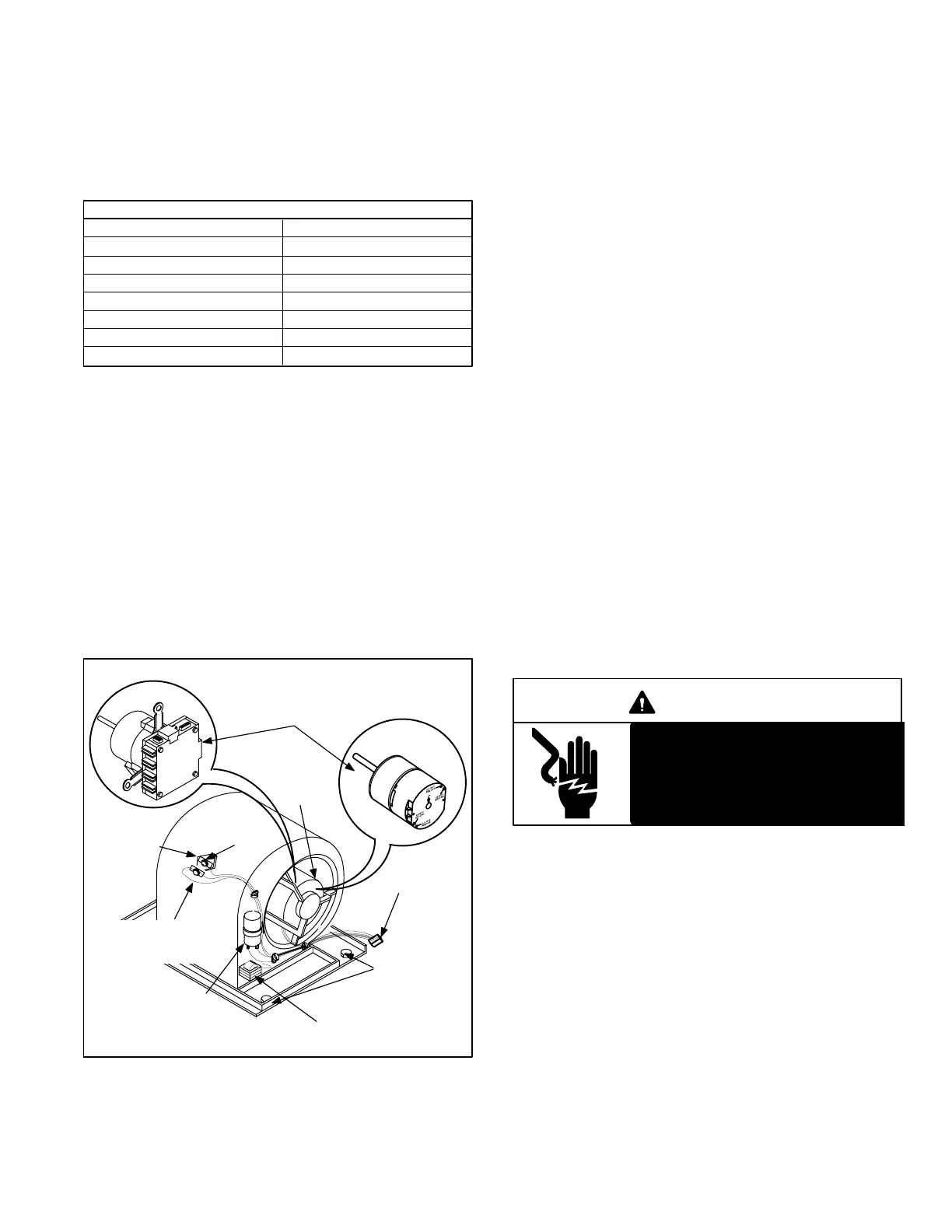
D − Secondary Limit S21 (Reverse Flow Units
Only) Figure 17
S21 is a SPST N.C. manual reset limit wired in series with
ignition control A3. It is located on the blower housing. If the
blower should fail to operate or if return or supply airway be
comes partially blocked, the blower housing would become
warm causing S21 to trip." S21 is set at 160°F and cannot
be adjusted. If S21 trips, it must be manually reset. Allow
adequate time for S21 to cool before attempting to reset.
CGA models use a selfresetting SPST N.C. limit that
opens at 130°F and closes at 110°F. Its function is the
same. This is a safety shut down function of the unit.
FIGURE 17
BLOWER ASSEMBLY
RESET
BUTTON
SECONDARY
LIMIT S21
Q" MODEL
BLOWER
MOTOR
HARNESS
CONNECTOR
2 MOUNTING
BOLTS
AUXILIARY
FAN CONTROL
S71
V" MODEL
BLOWER MOTOR
BLOWER MOTOR
CAPACITOR Q"
MOTORS ONLY
COIL CHOKE V" MOTORS ONLY
(EXCEPT EARLY V3 MODELS)
E − Auxiliary Fan Control (S71) (Reverse Flow
Units Only) Figure 17
An auxiliary fan control (S71) is located on the blower hous
ing. It protects secondary limit (S21) from tripping." S71
actuates at 140°F. In both Q and V units, if S71 actuates
(closes) the blower is forced to operate.
1 − GSR21Q" Applications (S71)
S71 is a normally open SPST selfresetting control
wired in parallel with blower relay K361. On a tem
perature rise S71 closes energizing blower B3 on
heating tap speed.
2 − GSR21 V" Applications (S71)
S71 is a normally open SPST selfresetting control
wired in series with 24 VAC from transformer T1. S71
closes and S78 opens on a temperature rise (see
table 6). When S71 closes, pin 11 on the VSP2 and
pin 12 on the VSP1 is energized. When S78 opens,
pin 11 on the VSP2 and pin 12 on the VSP1 is ener
gized. When pin 11 on the VSP2 or pin 12 on the
VSP1 is energized, the blower operates on low
speed (heat/cool) tap.
Secondary limit (S21) and auxiliary fan control (S71) work
together to reduce excessive temperature in the blower
end of unit. First, as temperature rises in the blower
compartment and nears 140°F, S71 actuates the blower in
an attempt to reduce temperature. If temperatures contin
ue to rise, S21 will trip" and ignition control A3 is de ener
gized.
DANGER
Shock Hazard. Auxiliary fan control
is connected to line voltage. Before
servicing control, be sure to dis
connect power to unit. Can cause
injury or death.
F − Ignition Control (A3)
An electronic direct spark ignition control (A3) with flame
rectification sensing is used on all G21/GSR21 units. See
figures 18 and 19. G21 and GSR21 series may be factory
equipped with Lennox GC1, Lennox GC3, or Johnson
G891 ignition control modules. Ignition controls are inter
changeable. Refer to Service and Application Notes.
For additional safety and troubleshooting convenience, the
ignition control modules selftest their internal safety circuits
continuously and use the diagnostic LED to indicate control
failure. The light helps the technician troubleshoot the unit by
indicating an unusual condition.
 Loading...
