Page 30
P − ICM1 and ICM2 BLOWER MOTOR
(G21V/GSR21V Units)
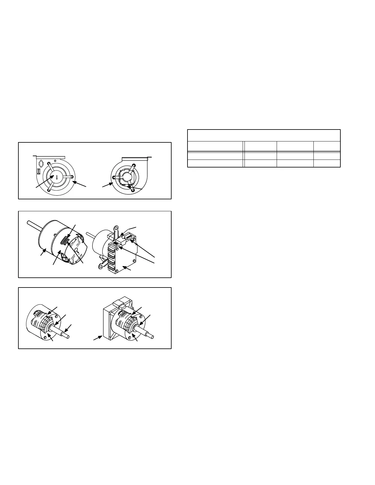
G21V/GSR21V units use a threephase, electronically con
trolled d.c. brushless motor (controller converts single phase
a.c. to three phase d.c.), with a permanentmagnettype rotor
(figures 33 and 34). Because this motor has a permanent
magnet rotor it does not need brushes like conventional D.C.
motors. ICM motors consist of a control module and motor.
The ICM control module can be replaced separately from the
motor if necessary. However, if the motor fails the motor/mod
ule assembly must be replaced. Internal components are
shown in figure 35. The stator windings are split into three
poles which are electrically connected to the controller. This ar
rangement allows motor windings to be turned on and off in
sequence by the controller.
G21V/GSR21V MOTOR BLOWER HOUSING
MOTOR
BLOWER
HOUSING
FIGURE 33
MOTOR
FIGURE 34
G21V/GSR21V BLOWER MOTOR B3
MOTOR
CONTROLLER
SHAFT
J49
J48
CONTROLLER
SPEED TAPS
(under cover
slides open
after power
plug is re
moved)
J49
J48
G21V/GSR21V BLOWER MOTOR COMPONENTS
FIGURE 35
STATOR
(WINDINGS)
OUTPUT
SHAFT
BEARING
ROTOR
STATOR
(WINDINGS)
BEARING
CONTROLLER
ROTOR
The controller is primarily an a.c. to d.c. converter. Con
verted d.c. power is used to drive the motor. The control
ler contains a microprocessor which monitors varying
conditions inside the motor (such as motor workload).
The controller uses sensing devices to know what position
the rotor is in at any given time. By sensing the position of
the rotor and then switching the motor windings on and off
in sequence, the rotor shaft turns the blower.
G21V/GSR21V series blower motor ratings are listed in table
11. All G21V/GSR21V blower motors use single phase pow
er. An external run capacitor is not used. The motor uses per
manently lubricated balltype bearings.
TABLE 11
ELECTRONICALLY CONTROLLED BLOWER MOTOR
CCW ROTATION
Unit Volts Phase HP
G21V3/GSR21V3 120 1
1
1/2
1G21V5/GSR21V5 120
Internal Operation
Each time the controller switches a stator winding (figure 35)
on and off, it is called a pulse." The length of time each pulse
stays on is called the pulse width." By varying the pulse width
(figure 36), the controller varies motor speed (called pulse
width modulation"). This allows for precise control of motor
speed and allows the motor to compensate for varying load
conditions as sensed by the controller. In this case, the con
troller monitors the static workload on the motor and varies
motor rpm in order to maintain constant airflow (cfm).
ICM1 motor is equipped with 11 incremental taps which are
driven by the integral controller. The controller is capable of
controlling three of the 11 taps.
The VSP2 control gives the ICM2 eight different options for
cfm for heat or cool call. Figure 13 shows four pin selec
tions for High/Cool speed and four pin selections for Heat
speed. In addition there is four pin selections for Low speed
which can be used for either Heat or Cool.
 Loading...
