Page 22
IMPORTANT
When the GC1 is operating normally the LED will not
be lit. If it is lit refer to Ignition Control Troubleshoot
ing Flowchart in the back of manual.
The GC1 ignition control LED may be lit for the following rea
sons: lockout condition (lit), postpurge operation (lit) or con
trol failure (lit). If the control is in lockout (lit) due to unsuccess
ful ignition (five tries), it must be reset by breaking and remak
ing thermostat demand or power to the unit. The GC1 is
equipped with a Safety Dormant Lockout circuit (sleep
mode). This circuit continuously monitors the control for inter
nal circuit faults. In addition the Safety Dormant Lockout cir
cuit senses potentially damaging frequency, voltage or cur
rent. If lockout is due to a selftest failure, or if damaging fre
quency, voltage or current has been sensed, the GC1 will go
into a Safety Dormant Lockout (LED lit). The control will be
shut off. The GC1 control may or may not have been dam
aged. The control can only be reset by breaking and remak
ing power to the unit.
IMPORTANT
When the GC3 and the G891 are operating normal
ly the LED will be lit at all times. If it is not lit or if it
is flashing refer to Ignition Control Troubleshooting
Flowchart in the back of manual.
If any of the the GC3 or the G891 model no. 86H3001 or
34K8301 control is in lockout (LED flashing) due to unsuc
cessful ignition (five tries), breaking and remaking thermostat
demand or power to the unit will reset the control. The later
G891 control (model no. 73K8601) has two flashing modes. If
LED is flashing 0.5 seconds on and 2.5 seconds off, the control
is in lockout due to unsuccessful ignition (five tries). To reset
the control break and remake thermostat demand to the unit. If
LED is flashing 0.1 seconds on and 0.1 seconds off (flickering)
the control reads a low flame sense. Inspect sensor and refer
to Troubleshooting Flowchart in back of manual. If the LED is
not lit, break and remake power to unit. If LED is still not lit refer
to Ignition Control Troubleshooting Flowchart in back of manu
al. The GC3 and G891 do not have Safety Dormant Lockout
circuit.
Watchguard
All G21 / GSR21 units are equipped with a watchguard circuit.
The GC1 uses a separate external watchguard WG1 control
board (A18) located above the control box. The GC3 and
G891 ignition control incorporate this function.
The watchguard feature serves as an automatic reset de
vice for ignition controls locked out because the furnace
has failed to ignite.
The external watchguard used with the GC1 ignition control
will break and remake thermostat demand after one hour of
continuous thermostat demand, (unit locked out or operation
al). This will reset the ignition control to attempt ignition.
The internal watchguard used with the GC3 and the G891 is
activated only when the unit has failed to light. The internal
watchguard is activated after the fifth unsuccessful ignition trial.
Internal watchguard will reset the ignition control one hour after
the unit has locked out.
DANGER
Shock Hazard. Spark related com
ponents contain high voltage. Dis
connect power before servicing
unit. Ignition control is not field re
pairable. Can cause injury or
death.
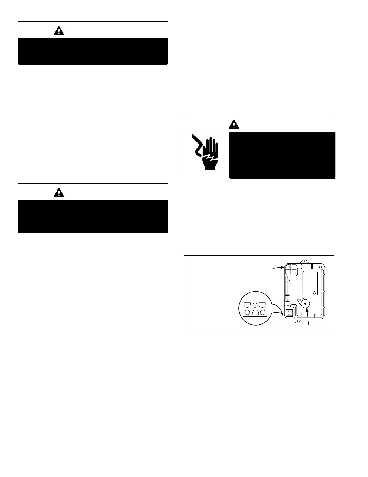
1 − Lennox GC1 Ignition Control (Figure 18)
The Lennoxbuilt GC1 ignition control (A3) has a black
plastic cover, and is illustrated in figure 18. The unit wiring
harness (P72) plugs directly into the jack (J72) at the cor
ner of the control. A diagnostic lockout indicator light, a red
LED, is visible through the GC1 cover.
Spark wire connection is made to a spark plug type connec
tor on the control. Sensor wire connection is made to a
quick connect terminal.
GC1 IGNITION CONTROL
RED
LED
SENSE TERMINAL
SPARK PLUG WIRE CONNECTION
123
45 6
1 24 VAC FROM TSTAT W"
2 COMMON
3 24 VAC TO GAS VALVE
4 24 VAC INPUT FROM
TRANSFORMER T1
5 120 VAC TO PURGE
BLOWER
6 120 VAC INPUT
J72 CONNECTOR
FIGURE 18
2 − Lennox GC3 Ignition Control (Figure 19)
The Lennoxbuilt GC3 ignition control (A3) has a white or a
green plastic cover, and is illustrated in figure 19. The unit
wiring harness (P72) plugs directly into the jack (J72) at the
bottom of the control. A diagnostic indicator light, a green
LED, is visible through the GC3 cover.
 Loading...
