Page 26
H − Differential Pressure Switch (Figure 26)
The differential pressure switch is mounted in the heating
compartment [see unit components illustration (page 10)
for exact location]. It is connected to the air intake and ex
haust outlet by separate lengths of flexible plastic tubing.
Note that each flexible hose connects to the barbed fitting
at the differential pressure switch. See figure 26. Each fit
ting has a popin orifice of 0.016" I.D.
FIGURE 26
DIFFERENTIAL PRESSURE SWITCH
TERMINAL
CONNECTIONS
TO EXHAUST OUTLET
BARBED FITTING
TO AIR DECOUPLER
BOX
BARBED FITTING
0.016 I.D.
ORIFICE (2)
NOTE: FITTINGS
POINTED DOWNWARD
FOR HOSE DRAINAGE
ORIFICE PRESSES
INTO PLACE
Each orifice is critical to switch operation. The ori
fice reduces extreme positive and negative pres
sure peaks" and must be used to prevent erratic
switch operation. Do not remove orifice from
barbed fitting in pressure switch.
IMPORTANT
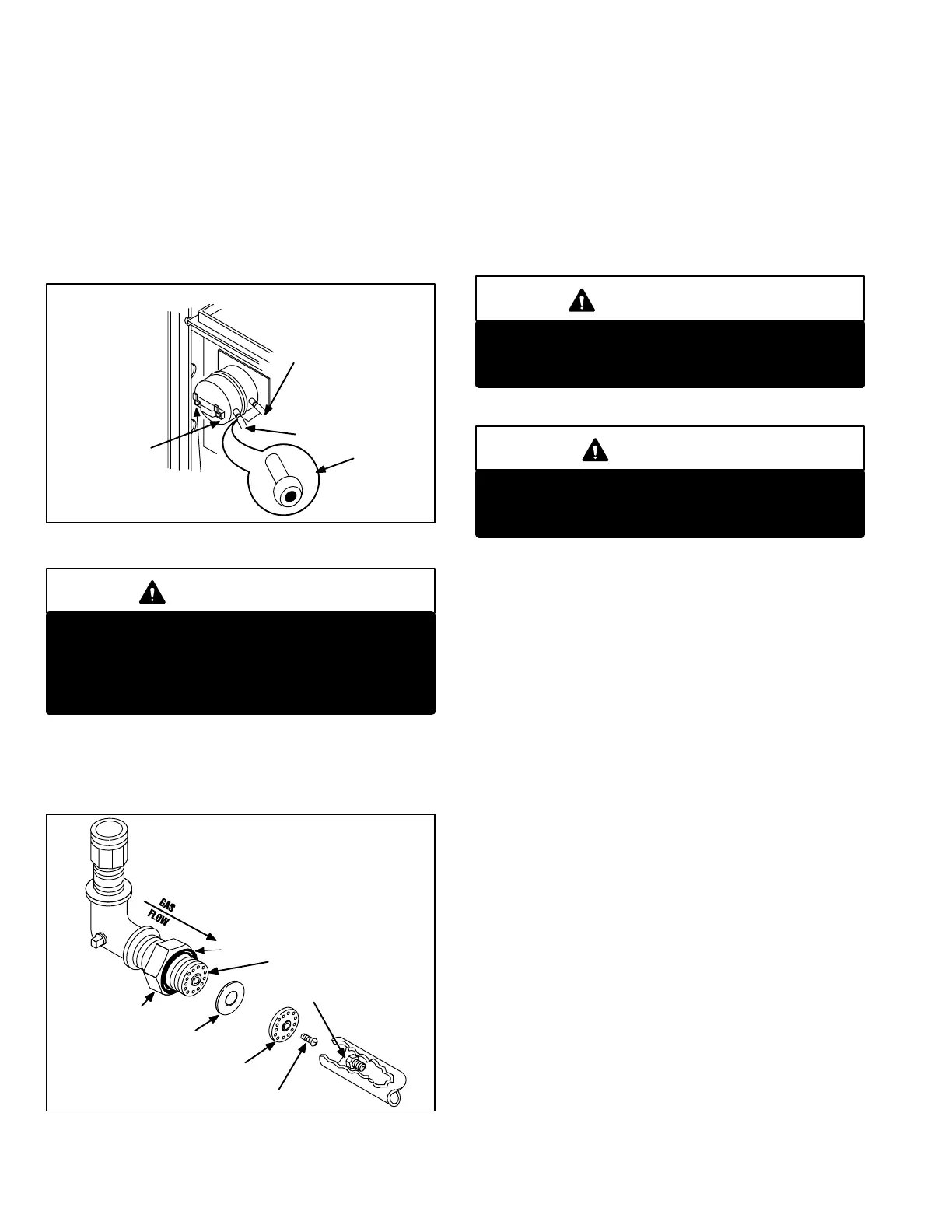
I − Gas Intake FlapperValve & Orifice
(Figure 27)
FIGURE 27
GAS INTAKE FLAPPER VALVE
ASSEMBLY
ORING
CLEARANCE
PLATE/SPACER
SCREW
ORIFICE
GAS
MANIFOLD
FLAPPER
VALVE BODY
CLEARANCE
PLATE/SPACER
ELBOW
1 − Gas Intake Flapper Valve & Assembly
A union at the bottom of the expansion tank provides for re
moval of gas flapper valve assembly and orifice access.
The flapper moves freely over a spacer and is opened
against the clearance plate by incoming gas pressure.
Back pressure from each combustion pulse forces the flap
per against the valve body closing off gas supply.
Refer to troubleshooting section for specific information
about flapper valve inspection and conditions requiring re
placement.
IMPORTANT
Disconnect gas pipe at union. Tighten until bush
ing seats in orifice housing and gas pipe is in verti
cal position.
2 − Orifice
WARNING
Standard atmospheric burner orifices or orifice
blanks cannot be used as replacements in
G21/GSR21 units.
Each G21/GSR21 unit uses only one orifice located down
stream of the flapper valve and sized specifically for each
unit. Refer to Service and Application notes for specific ori
fice size for each unit.
J − Air Intake Chamber & Purge Blower
1 − Air Intake Chamber
An air intake chamber houses the purge blower and air in
take flapper valve assembly. Air enters through the air in
take pipe (center of mullion), passes through the purge
blower and the flapper valve to the combustion chamber.
The entire air intake chamber is mounted on a large seal
pad to eliminate vibration.
2 − Purge Blower
The purge blower has a 120 volt motor and is permanently
lubricated. It is powered during pre and postpurge and
ignition. After the sensor proves flame, the purge blower is
deenergized and air is drawn through the blower by nega
tive pressure. During combustion the blower is not pow
ered.
K − Air Intake Flapper Valve
The air intake flapper valve is similar to the gas flapper
valve in operation. A flapper moves freely over a spacer be
tween two plates. In actual operation, the flapper is forced
against the clearance plate by the purge blower allowing air
to enter the combustion chamber. Next, back pressure
from combustion forces the flapper against the cover plate
closing off the air supply. Finally, as a negative pressure is
 Loading...
