Page 34
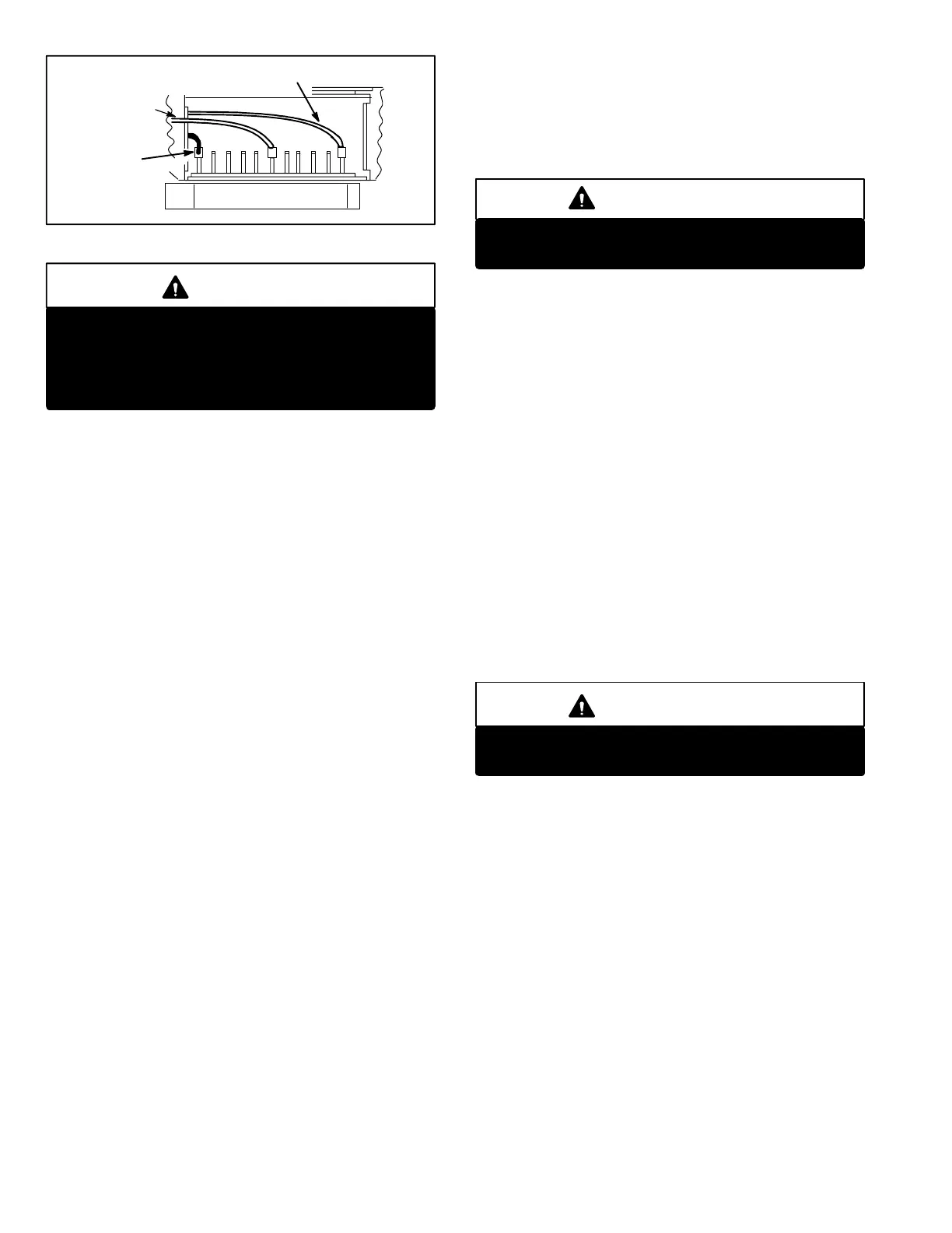
TYPICAL VIEW SHOWN (CONNECTORS MAY NOT BE IN THIS ORDER)
FIGURE 39
HIGH SPEED HEAT
RED CONNECTOR
LOW SPEED HEAT/COOL WHITE CON
NECTOR
HIGH SPEED
COOL−BLACK
CONNECTOR
CFM
TAP
HIGH
LOW
1
2
3
4
5
6
7
8
9
10
11
BLOWER B3 SPEED TAPS
DANGER
Do not attempt to repair electronically controlled
blower motor or VSP1. There are no field serviceable
parts. If either component appears to be faulty after
following checkout procedure, replace entire com
ponent then recheck for proper operation.
b − Heating Mode (Three Modes)
1− SingleStage Heating
The HB" and W2" terminals are jumpered to
gether. DS1 (ON/OFF) and DS2 (HEAT) LEDs
are lit to indicate the blower is operating in heat
ing speed (high speed heat tap). These LEDs
are lit after 75 seconds (30 seconds pre−purge
and 45 seconds fanon time) from the time a call
for heat is made.
2− Two−Stage Heating
The DS1 LED is lit to indicate blower operation
in first stage heat (low speed heat/cool tap). It is
energized 75 seconds (30 seconds pre−purge
and 45 seconds time ON" delay) after W1" ter
minal is energized from thermostat terminal
W1."
DS1 and DS2 LEDs are lit to indicate blower op
eration in second stage heat (high speed heat tap).
Second stage heat signal is applied to W2" from
W2" terminal of thermostat.
3− Harmony Heating
Blower speed is controlled by the PWM (pulse
width modulation) signal sent from the master con
trol of the Harmony zoning system to the terminal
strip’s DS" terminal. DS1 and DS3 LEDs are lit to
indicate the blower is operating. Harmony over
rides blower speed taps. Blower speed varies ac
cording to zone demand.
c − Cooling Mode (Five Modes)
1 − Non−Zoned Units With Single−Speed
Compressor Without CCB1
Terminals DS" and G" must be jumpered to
gether. This forces the blower to run on the high
speed cool tap. DS1 and DS3 LEDs are lit to in
dicate blower operation on the high speed cool
ing tap.
2 − Non−Zoned Units With Two−Speed
Compressor Without CCB1
IMPORTANT
Y2" must be jumpered to DS" in two−speed, non−
zoned applications when CCB1 is not used.
The ON/OFF LED DS1 is lit to indicate the blow
er is operating on the low speed heat/cool tap.
DS1 is energized when a 24VAC thermostat de
mand is supplied to the control (terminal G" on
the control box terminal strip). The ON/OFF LED
(DS1) and speed regulation LED (DS3) are lit to
indicate blower is operating on high speed cooling
tap (24VAC is supplied to the unit terminal strip
Y2" from Y2" on the thermostat). Jumper termi
nals DS and Y2 together when CCB1 is not used.
3 − NonZoned Single Speed and Two Speed
Units With CCB1
Terminal DS connects to the DS output from the
CCB1. The blower speed is controlled by the DC
signal from the CCB1. The ON/OFF LED (DS1)
is lit to indicate the blower is operating on the low
speed heat/cool tap. The ON/OFF LED (DS1)
and the speed regulation LED (DS3) are lit to in
dicate the blower is operating on the high speed
cooling tap.
IMPORTANT
Never jumper Y2" to DS" when CCB1 is used.
Damage to the CCB1 control will occur.
4 − Zoned Units with SingleSpeed
Compressor
Blower speed is controlled by a PWM (pulse
width modulation) signal sent from the master
control of the zoning system to the terminal
strip’s DS" terminal. DS1 and DS3 LEDs are lit
to indicate blower operation. Harmony overrides
blower speed taps. Blower speed varies according
to zone demand.
5 − Zoned Units with Two−Speed
Compressor
Blower speed is controlled by the PWM (pulse
width modulation) signal sent from the master con
trol of the zoning system to the terminal strip’s DS"
terminal. DS1 and DS3 LEDs are lit to indicate the
blower is operating. Harmony overrides blower
speed taps. Blower speed varies according to zone
demand.
 Loading...
