FIGURE 64
TRANSDUCER
(PART #78H5401)
Page 48
To Measure Flame Signal−GC1 Ignition Control:
WARNING
Fire and explosion hazard.
These instructions MUST be followed exactly.
Can cause a fire or explosion resulting in property
damage, personal injury or loss of life.
GC1 FLAME SIGNAL TEST
FIGURE 63
IGNITION
CONTROL
SENSE" TERMINAL
SENSOR
WIRE
D.C.
MICROAMP
METER
FLAME SENSOR
(+)(−)
1 − Place meter in series between ignition control and sen
sor wire. Connect positive (+) lead of meter to ignition
control sensor connection and negative (−) lead of the
meter to sensor wire. See figure 63.
2 − Set thermostat for a heating demand and check flame
signal with unit operating. For G21/GSR21 series with
the GC1 ignition control (A3), a reading of 3 to 5 micro
amps DC is typical. The control will operate between 1
and 5 microamps DC.
Flame signal may rise above 3 to 5 microamps for the first
few seconds after ignition and then level off.
To Measure Flame Signal−GC3/G891 Ignition Controls:
A transducer (Part
#78H5401 avail
able from Lennox
Repair Parts) is re
quired to measure
flame signal on
GC3 / G891
equipped units.Seefigure 64. The transducer con
verts microamps to volts on a 1:1 conversion. GC3
flame signal is 1.5−2.5 microamps, therefore a read
ing of 1.5−2.5 volts should be read on the meter. G891
flame signal is 1.2−2.2 microamps, therefore a read
ing of 1.2−2.2 volts should be read on the meter. The
transducer plugs into the meter. See figure 66 for
proper use of transducer.
1 − Set the volt meter to the DC voltage scale. Insert
transducer into the VDC and common inputs. Ob
serve correct polarities. Failure to do so results in neg
ative (−) values.
2 − Turn off supply voltage to control.
3 − Disconnect flame sensor lead from terminal of ignition
control.
4 − Connect (+) lead of transducer to ignition control sen
sor connection. See figure 65.
5 − Connect (−) lead of the transducer to sensor wire. See
figure 65.
6 − Turn supply voltage on and close thermostat con
tacts to cycle system.
7 − When unit lights read voltage on meter display. Re
member 1 DC volt = 1 DC microamp. For G21/GSR21
series with the GC3 ignition control (A3), a reading of
1.5−2.5 volts DC should occur. For G21/GSR21 series
with the G891 ignition control (A3), a reading of 1.2−2.2
volts DC should occur.
SENSOR
WIRE
FIGURE 65
IGNITION
CONTROL
SENSE" TERMINAL
DIGITAL
METER
FLAME SENSOR
GC3 FLAME SIGNAL TEST
(+)
(−)
TRANSDUCER
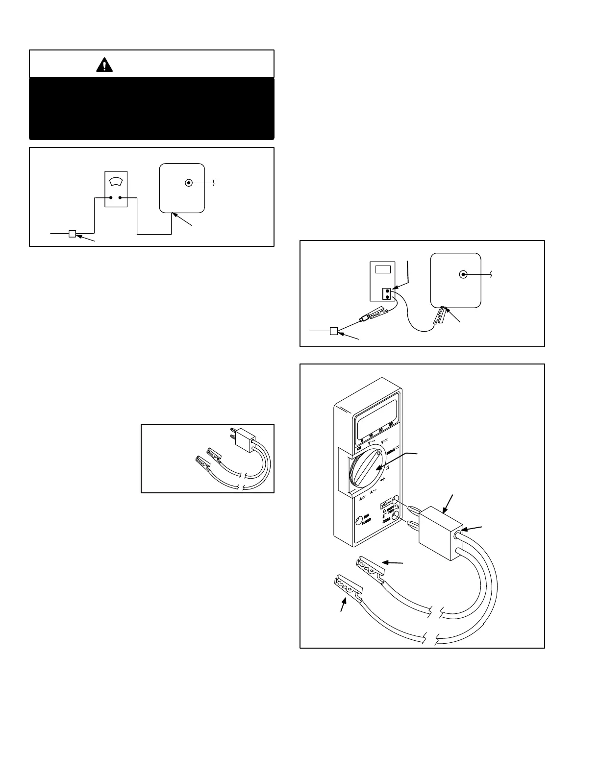
FIGURE 66
TRANSDUCER USAGE
1 − Set meter to DC voltage scale.
2 − Insert transducer into the VDC and
Common inputs. Observe polarities
3 − Connect (+) end of transducer lead to
GC3 sensor terminal.
4 − Connect (−) end to sensor wire.
TRANSDUCER
PART no. 78H5401
(+) TO GC3
SENSOR
TERMINAL
SET DIAL TO MEASURE
VDC
(+)
(−)
(−) TO
SENSOR WIRE
NOTE−MUST USE
DIGITAL METER
RED COLLAR
INDICATES
POSITIVE
LEAD
 Loading...
