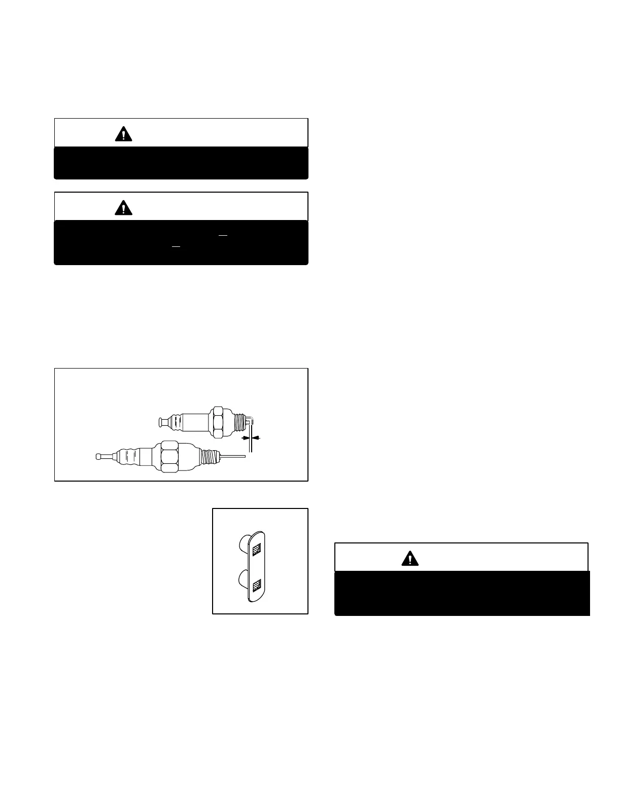
SPARK PLUG/SENSOR
REMOVAL TOOL
LENNOX PART # 20H43
FIGURE 29
Page 27
created in the combustion chamber, the flapper is drawn to
the clearance plate and air enters. Once ignition has oc
curred, back pressure and negative pressure control the
flapper valve with each combustion pulse.
L − Spark Plug & Sensor (Figure 28)
IMPORTANT
Units with GC3 ignition controls require a ceramic
resistor spark plug.
IMPORTANT
The spark plug is torqued to 130 + 5 foot/lbs. The
sensor is torqued to 85 + 5 foot/lbs. Allow metal to
cool before measuring torque.
The spark plug is used in conjunction with the primary con
trol for igniting the initial gas and air mixture and is only
used during startup.
Figure 28 gives the proper spark gap setting. Note the un
usual electrode angle in comparison to other spark plug ap
plications. A feeler gauge can be used to check the gap.
FIGURE 28
NOTE Carbon resistor type
plugs should not be used.
CHAMPION FI21500 or
equivalent only
SPARK PLUG
.113 to .118
SENSOR
Temperatures in the combustion
chamber keep the plug free from ox
ides. It should not need regular
maintenance. Compression rings
are used to form a seal to the cham
ber.
The spark plug type sensor has a
single electrode (no ground strap).
Compression rings are used to
form a seal to the chamber. It also should not need regular
maintenance. Removal of the plug/sensor is aided by a
Lennox spark plug/sensor removal tool. See figure 29. It is
available from Lennox Repair Parts, part no. 20H43.
The spark plug and sensor are located on the left side of the
combustion chamber, see figures 30 and 31 for exact loca
tion. The sensor is the top plug and is longer than the spark
plug. The spark plug is in the lower position. Plugs cannot be
interchanged due to different thread diameters.
M − Combustion Chamber & Heat Exchanger
Assembly (Figures 30 and 31)
1 − Combustion Chamber
The combustion chamber has gas and air intake manifolds.
See figures 30 and 31 for exact location. Exhaust gas leaves
through the tailpipe at the top of the chamber.
2 − Tailpipe
The tailpipe connects the combustion chamber to the exhaust
gas decoupler. The tailpipe and decoupler create the proper
amount of back pressure for combustion to continue and are
major heat exchanger components. The resonator provides
attenuation for acoustic frequencies. See figures 30 and 31
for exact location.
3 − Exhaust Decoupler
The exhaust decoupler is manifolded into the condenser
coil. Latent heat of combustion is extracted from exhaust
gas in the condenser coil. When this is done, condensate
(moisture) is produced. The circuiting of the coil allows for
proper drainage of condensate to the exhaust outlet line.
See figures 30 and 31 for exact location.
4 − Heat Exchanger Assembly
Each unit input size uses a specific heat exchanger assem
bly. Externally, they may appear the same, but THEY
MUST NOT BE INTERCHANGED between unit input
sizes. Internal characteristics related to unit input properly
match each assembly for unit input rating. See figures 30
and 31 for exact location.
The entire heat exchange assembly is mounted on rubber
isolation mounts to eliminate vibration.
IMPORTANT
If heat exchanger must be replaced, keep orifice
from the old heat exchanger. New orifices are not
supplied with replacement heat exchangers.
N − Gas & Air Components Applied to Heat
Exchanger
Figures 30 and 31 identify all of the components of the ba
sic heating assembly.
 Loading...
