Page 28
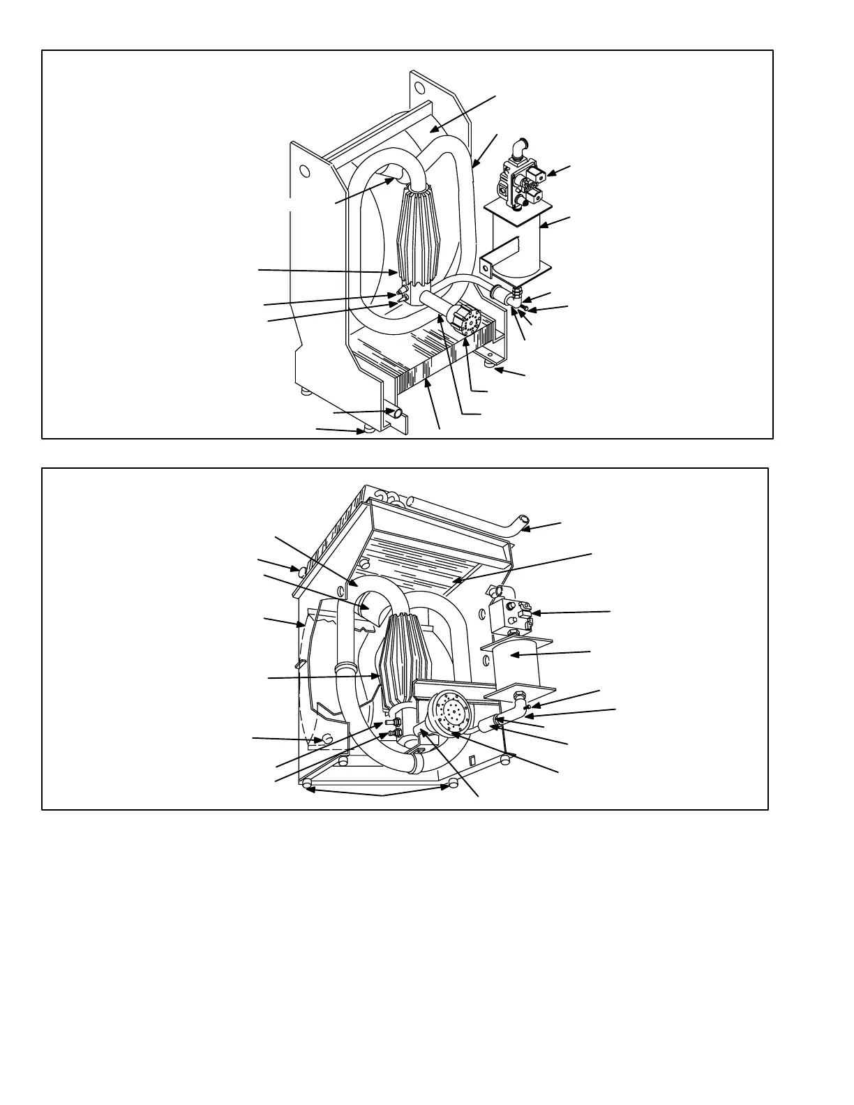
FIGURE 30
G21 COMBUSTION COMPONENTS
COMBUSTION
CHAMBER
SENSOR
SPARK PLUG
VALVE BODY & AIR FLAPPER VALVE ASSEMBLY
ORIFICE (INSIDE)
GAS INTAKE MANIFOLD &
FLAPPER VALVE ASSEMBLY
EXPANSION
TANK
GAS VALVE
EXHAUST DECOUPLER
CONDENSER COIL
RESONATOR
TAILPIPE
EXHAUST OUTLET MANIFOLD
RUBBER ISOLATION MOUNTS (4)
AIR INTAKE MANIFOLD
ELBOW
PRESSURE TAP
RUBBER ISOLATION MOUNTS (4)
FIGURE 31
GSR21 COMBUSTION COMPONENTS
COMBUSTION CHAMBER
DRAIN PLUG
SENSOR
SPARK PLUG
VALVE BODY & AIR FLAPPER
VALVE ASSEMBLY
ORIFICE (INSIDE)
GAS INTAKE MANIFOLD & FLAPPER
VALVE ASSEMBLY
EXPANSION TANK
GAS VALVE
EXHAUST DECOUPLER
COIL INLET MANIFOLD
RESONATOR
AIR INTAKE MANIFOLD
CONDENSER COIL
TAILPIPE
EXHAUST OUTLET MANIFOLD
RUBBER ISOLATION MOUNTS (4)
ELBOW
PRESSURE TAP
Combustion Procedure in G21/GSR21 Units:
1 − Gas flows through the valve, expansion tank, flapper
valve and orifice into the combustion chamber.
2 − Air flows through the air flapper valve and directly into
the combustion chamber. Spark occurs.
3 − Combustion takes place and exhaust gas flows
through the tailpipe, exhaust decoupler and condenser
coil to the exhaust outlet.
 Loading...
