Page 42
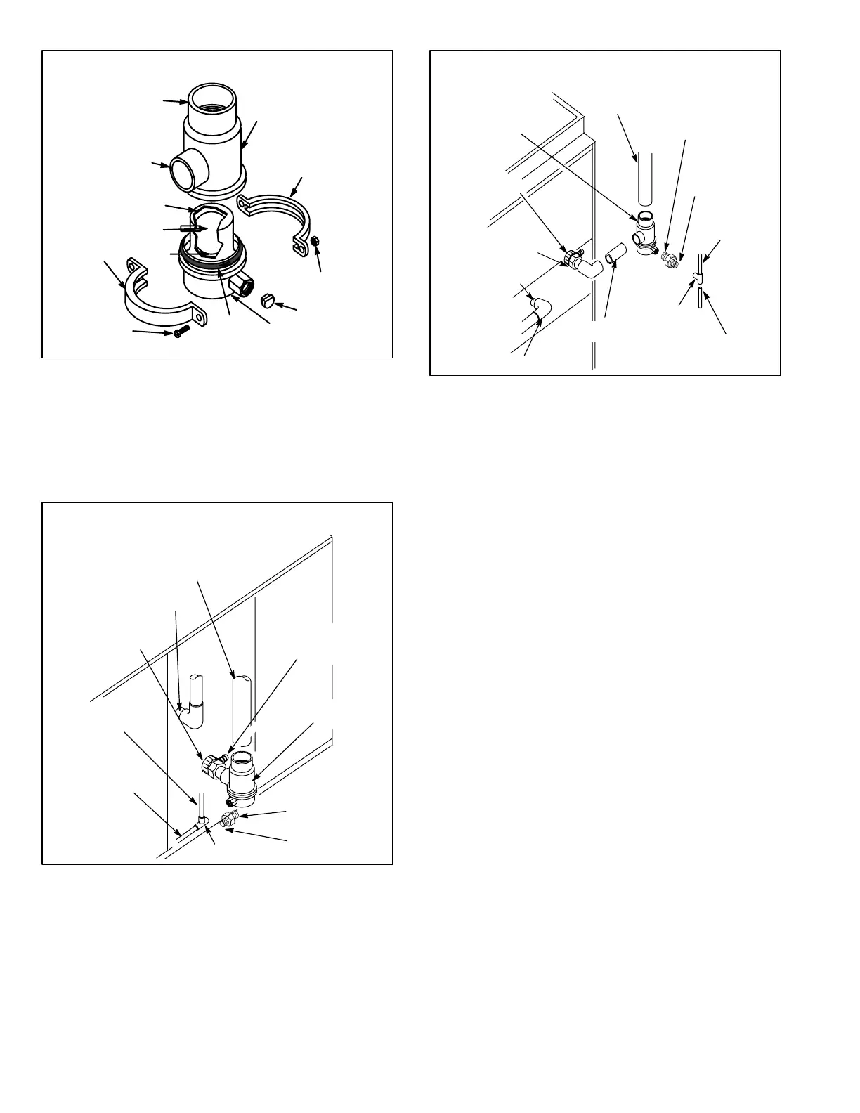
SEAT
FLOAT
FLOAT CAP
EXHAUST
OUTLET
HOUSING
BALL FLOAT CONDENSATE TRAP ASSEMBLY
G21 AND GSR21
CLAMP
NUT
(2 PROVIDED)
EXHAUST
INLET
CLAMP
O−RING
DAM
SCREW
(2) PROVIDED
TRAP ASSEMBLY
FIGURE 52
When installing a ball float trap, certain precautions should be
taken. Condensate trap housing must be cemented to the out
let exhaust pipe perpendicular with the bottom of unit to ensure
proper operation of trap float. Complete installation procedures
are outlined in GSR21 installation and operation instructions.
INTAKE
CONNECTION
COMPRESSION
COUPLING
1/2" X 5−1/2"
PVC VENT
1/2" PVC
CONDENSATE
DRAIN
1/2" PVC TEE
1/2" X 2"
PVC NIPPLE
1/2" PVC
MALE ADAPTER
BARBED FITTING
(Point toward
pressure switch)
EXHAUST PIPING
CONDENSATE
TRAP
BALL FLOAT CONDENSATE TRAP
(GSR21 HORIZONTAL APPLICATION)
FIGURE 53
CONDENSATE
TRAP
EXHAUST PIPE
COMPRESSION
COUPLING
BARBED FITTING
(Point toward
pressure switch)
INTAKE
CONNECTION
1/2"
PVC TEE
1/2" X 2"
PVC NIPPLE
1/2" PVC
MALE ADAPTER
1/2" PVC ELBOW
1/2" PVC
CONDENSATE
DRAIN
1/2" X 5−1/2"
PVC VENT
1−1/2" PVC
EXHAUST NIPPLE
BALL FLOAT CONDENSATE TRAP
(GSR21 DOWNFLOW APPLICATION)
FIGURE 54
Service Procedures for Ball Float
Condensate Trap
1 − Remove screws and clamps from condensate trap as
sembly.
2 − Lower trap assembly from housing. Care should be
taken not to crack seal from housing to exhaust pipe
and compression coupling.
3 − Disconnect trap assembly from condensate line.
4 − Remove float cap, float, seat, and oring and visually
inspect for cuts or breakdown of material. If seat, float
or oring are worn, a G21/GSR21 Condensate Trap
Parts Replacement Kit is available from Lennox Repair
Parts.
5 − Use a 1/4" hex wrench, remove plastic dam located in
condensate line connection of trap assembly. Check
interior of trap assembly for debris.
6 − Clean trap assembly with a mild soap and rinse thor
oughly.
7 − Carefully reinstall dam, seat, float, float cap, and oring
to trap assembly. If float cap does not snap closed, the
entire trap assembly must be replaced.
8 − Connect trap assembly to condensate line.
9 − Lubricate oring with water or silicone based lubricant
and reinstall trap assembly to housing. Using existing
clamps and screws, secure trap assembly to housing.
 Loading...
