Page 51
TABLE 16
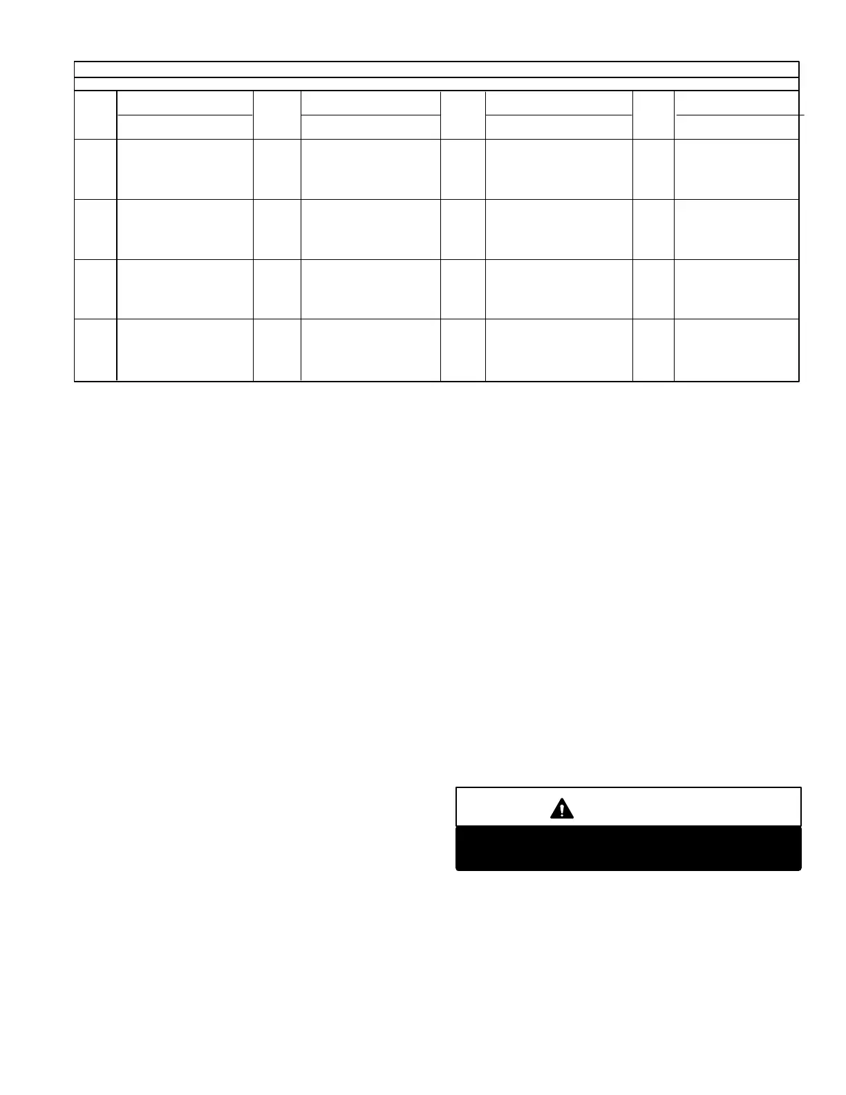
METER FLOW RATE
GAS RATE CUBIC FEET PER HOUR
Secs
for
One
Rev.
1
cu. ft.
2
cu. ft.
5
cu. ft.
Secs
for
One
Rev.
1
cu. ft.
2
cu. ft.
5
cu. ft.
Secs
for
One
Rev.
2
cu. ft.
5
cu. ft.
Secs
for
One
Rev.
Size of Test Dial
10 360 720 1800
11 327 655 1636
12 300 600 1500
13 277 555 1385
14 257 514 1286
15 240 480 1200
34 106 212 529
35 103 206 514
36 100 200 500
37 97 195 486
38 95 189 479
39 92 185 462
62 116 290
64 112 281
66 109 273
68 106 265
70 103 257
72 100 250
165 − 109
170 − 106
175 − 103
180 − 100
− − −
2
cu. ft.
5
cu. ft.
53 136 340
55 131 327
57 126 316
59 122 305
− − −
− − −
51 141 353
16 225 450 1125
17 212 424 1059
18 200 400 1000
19 189 379 947
20 180 360 900
21 171 343 857
22 164 327 818
23 157 313 783
24 150 300 750
25 144 288 720
26 138 277 692
27 133 267 667
28 129 257 643
29 124 248 621
30 120 240 600
31 116 232 581
32 113 225 563
33 109 218 545
52 69 138 346
54 67 133 333
56 64 129 321
58 62 124 310
60 60 120 300
− − − −
46 78 157 391
47 − 153 383
48 75 150 375
49 − 147 367
50 72 144 360
− − − −
40 90 180 450
41 − 176 439
42 86 172 429
43 − 167 419
44 82 164 409
45 80 160 400
100 72 180
102 − 176
104 69 173
106 − 170
108 67 167
98 − 184
86 84 209
88 82 205
90 80 200
92 78 196
94 − 192
96 75 188
74 97 243
76 95 237
78 92 231
80 90 225
82 88 220
84 86 214
110 − 164
112 64 161
116 62 155
120 60 150
125 − 144
130 − 138
135 − 132
140 − 129
145 − 124
150 − 120
155 − 116
160 − 113
Size of Test Dial Size of Test Dial Size of Test Dial
EXAMPLE:
a − One revolution of twofoot dial = 90 seconds.
b − Using the gas rate chart, table 16, note that 90 sec
onds = 80 cubic feet of gas per hour.
c − 80 cu. ft./hr. x 1000 Btuh/cu. ft. = 80,000 Btuh in
put.
d − Normally there are 1000 Btuh in each cubic foot of
gas. Make adjustment to this figure where the gas
heating value is other than 1000 Btuh per cubic
foot (contact the local gas supplier for local Btuh
per cubic foot ratings).
N − Checking Air Intake and Flapper Valve
Figures 70, 71 and 72
1 − Remove air intake chamber cover and check foreign
materials that may have accumulated, clean purge
blower and upper and lower chamber compartment if
necessary.
2 − Do not remove air flapper valve unless it is suspected
of being faulty.
If valve must be removed, carefully remove the eight
screws holding air intake flapper valve to valve body. DO
NO TURN OR REMOVE CENTER SCREW. Remove
valve from unit. CAUTIONDO NOT DROP.
3 − EXTREME CARE SHOULD BE TAKEN WHEN DISAS
SEMBLING INTERNAL COMPONENTS OF THE
VALVE. If taken apart, plates could be rotated out of
phase or reversed. Spacer thickness has an extremely
low tolerance. Note that each plate has a stamp of the
spacer thickness and a star or the words THIS SIDE
OUT." These stamps should all lie in the same quadrant
and face the outside of unit. See figures 71 and 72. New
er air flapper valve assemblies for the −40 / 50 / 60 / 80
contains a plate made from PPS thermoplastic with a
grooved surface on one side. The grooved surface should
be facing towards the flapper. Earlier −40/50/60/80 models
will have a stainless steel back plate with a star stamped
on the surface. This star must face away from the flapper
when assembled. On all −40/50/60/80 models, the front
plate will have a stamp and star on the surface and must
face away from flapper.
4 − Visually inspect flapper. On new units, the flapper may
not be perfectly flat, it may be curved or dished between
the plates. This is normal. On units that have had suffi
cient run in time, the flapper will be flat. If the flapper is torn,
creased or has uneven (frayed) edges, the material must
be replaced. A flapper material is available from Lennox
Repair Parts. Flapper should be replaced every four
years.
5 − To find potential warpage in the plates, check for the re
quired clearance between the flapper and back plate in
several places around the circumference of the valve.
See figure 73. Use a feeler gauge, starting small and
working up to the clearance dimension until the gauge
is just about snug.
WARNING
Do not force feeler gauge between flapper and
back plate. Damage to flapper material will occur.
Clearance should be checked in six or eight places
around the valve. If valve is out of clearance at any
one point, replace the assembly. Required clear
ance values are listed in table 17. Clearances are
updated regularly in Service and Application Notes.
 Loading...
