Lenze · 8400 BaseLine C · Reference manual · DMS 1.6 EN · 01/2014 · TD05 143
7 Drive application
7.3 Setting parameters (short overview)
_ _ _ _ _ _ _ _ _ _ _ _ _ _ _ _ _ _ _ _ _ _ _ _ _ _ _ _ _ _ _ _ _ _ _ _ _ _ _ _ _ _ _ _ _ _ _ _ _ _ _ _ _ _ _ _ _ _ _ _ _ _ _ _
7.5.6 PC
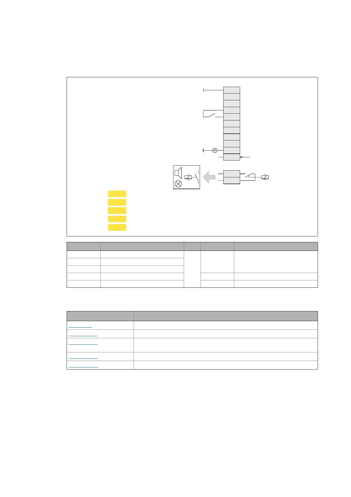
In this control mode, the control is executed via "free" parameters. The connection to inputs/out-
puts of the application takes place via the following system blocks:
Connection Assignment Connection Assignment
RFR LA_NCtrl.bFailReset A1U -
DI1 -
DI2 -
DI3 - NO, COM LA_NCtrl.bDriveFail
DI4 - DO1 LA_NCtrl.bDriveReady
System block Function
LS_DisFree
Any four 16-bit signals of the application can be displayed on display codes
LS_DisFree_a
Any four analog signals of the application can be displayed on display codes
LS_DisFree_b
Any eight digital signals of the application can be displayed on a bit-coded display
code
LS_ParFree_a
Output of 4 parameterisable analog signals
LS_ParFree_b
Output of 16 parameterisable digital signals
X101
NO
COM
GND
A1U
AR
RFR
DI1
DI2
DI3
DI4
24E
DO1
12I
X4
+
C472/1
C470/3
C470/4
C470/1
C470/2
Enable controller / reset error message
External supply 24 V DC
DriveFail
DriveReady
Speed setpoint
Selection of fixed setpoint 1/3
Selection of fixed setpoint 2/3
Manual DC-injection braking (DCB)
Direction of rotation CCw
 Loading...