Lenze · 8400 BaseLine C · Reference manual · DMS 1.6 EN · 01/2014 · TD05 127
7 Drive application
7.2 Interface description
_ _ _ _ _ _ _ _ _ _ _ _ _ _ _ _ _ _ _ _ _ _ _ _ _ _ _ _ _ _ _ _ _ _ _ _ _ _ _ _ _ _ _ _ _ _ _ _ _ _ _ _ _ _ _ _ _ _ _ _ _ _ _ _
7.2 Interface description
Tip!
You can change the preconfigured assignment of the respective input via the configuration
parameters given in the first column.
User-defined terminal assignment
( 114)
Inputs
Identifier
Data type
Configuration parameters
Information/possible settings
nMainSetValue_a
INT
C700/1
Main speed setpoint
• Scaling: 16384 ≡ 100 % reference speed (C011
)
• The main setpoint is transformed to a speed setpoint in the setpoint encoder via
a ramp function generator with linear or S-shaped ramps.
• Upstream to the ramp function generator, a blocking speed masking function
and a setpoint MinMax limitation are effective.
• For a detailed functional description see FB L_NSet
.
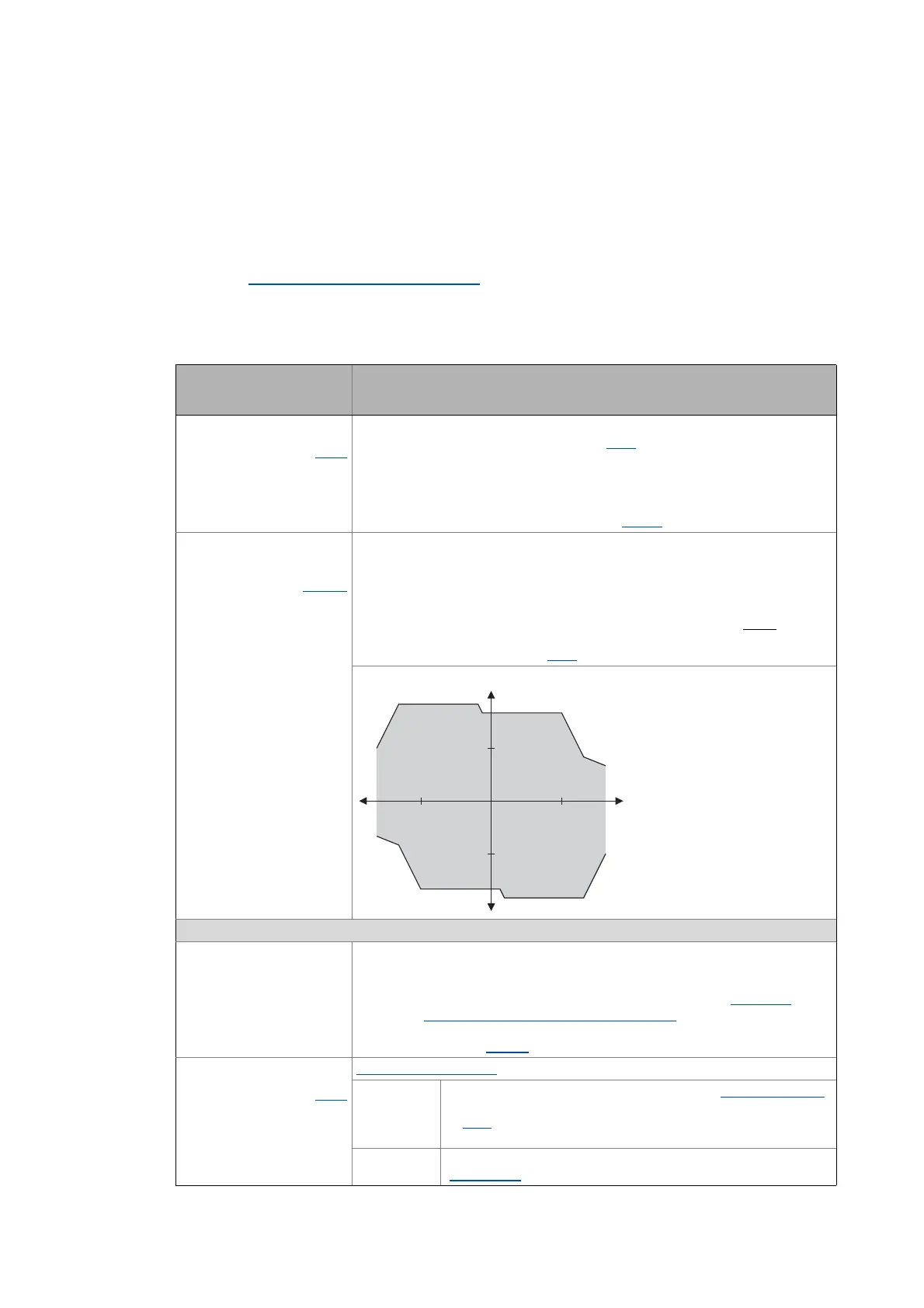
nTorqueMotLim_a
nTorqueGenLim_a
INT
C700/2...3
Torque limitation in motor mode and in generator mode
• These input signals are directly transferred to the motor control to limit the con-
troller's maximum torque in motor and generator mode.
• The drive cannot output a higher torque in motor/generator mode than set here.
• The applied values (any polarity) are internally interpreted as absolute values.
• If sensorless vector control (SLVC) is selected, the limitation has a direct
effect on
the torque-producing current component.
• Scaling: 16384 ≡ 100 % M
max
(C057)
Torque limits in motor and generator mode:
Device control
wCANControl
WORD
Control word via system bus (CAN)
• In the control mode "30: CAN", the controller controlled by a master control (e.g.
IPC) receives its control word by the CANopen system bus interface. The process
data word is provided at this input by the upstream port block LP_CanIn1
.
• See the "Process data assignment for control via CAN
" subchapter for a detailed
description of the individual control bits.
• Display parameter: C136/2
bCInh
BOOL
C701/1
Enable/Inhibit controller
FALSE Enable controller: The controller switches to the "OperationEnabled"
device state, if no other source of a controller inhibit is active.
• C158
provides a bit coded representation of all active sources/
triggers of a controller inhibit.
TRUE Inhibit controller (controller inhibit): The controller switches to the
"SwitchedON
" device state.
n
N
M
N
M
-M
N
-n
N
n
TorqueMotLim
TorqueGenLim
TorqueMotLim
TorqueMotLim
TorqueGenLim
 Loading...