Basic units in the power range 3 ... 11 kW
Mounting in ”cold plate” technique
5
Basic device installation
5.4
5.4.3
L
5.4-4
EDS82EV903-1.0-11/2002
5.4.3 Mounting in ”cold plate” technique
When using ”cold plate” technique the controllers can be mounted to sum
coolers. Use controllers of type E82CV... .
The following points are important to ensure a safe operation of the drive
controllers:
l Good thermal contact with the cooler:
– The contact area between the cooler and the drive controller must be at
least as large as the cooling plate of the drive controller.
– Plane contact area, deviation max. to 0.05 mm.
– The cooler and heatsink must be attached using all the screwed joints
that are specified.
l Thermal resistance R
th
according to table. The values are valid for operation
with the drive controllers under rated conditions.
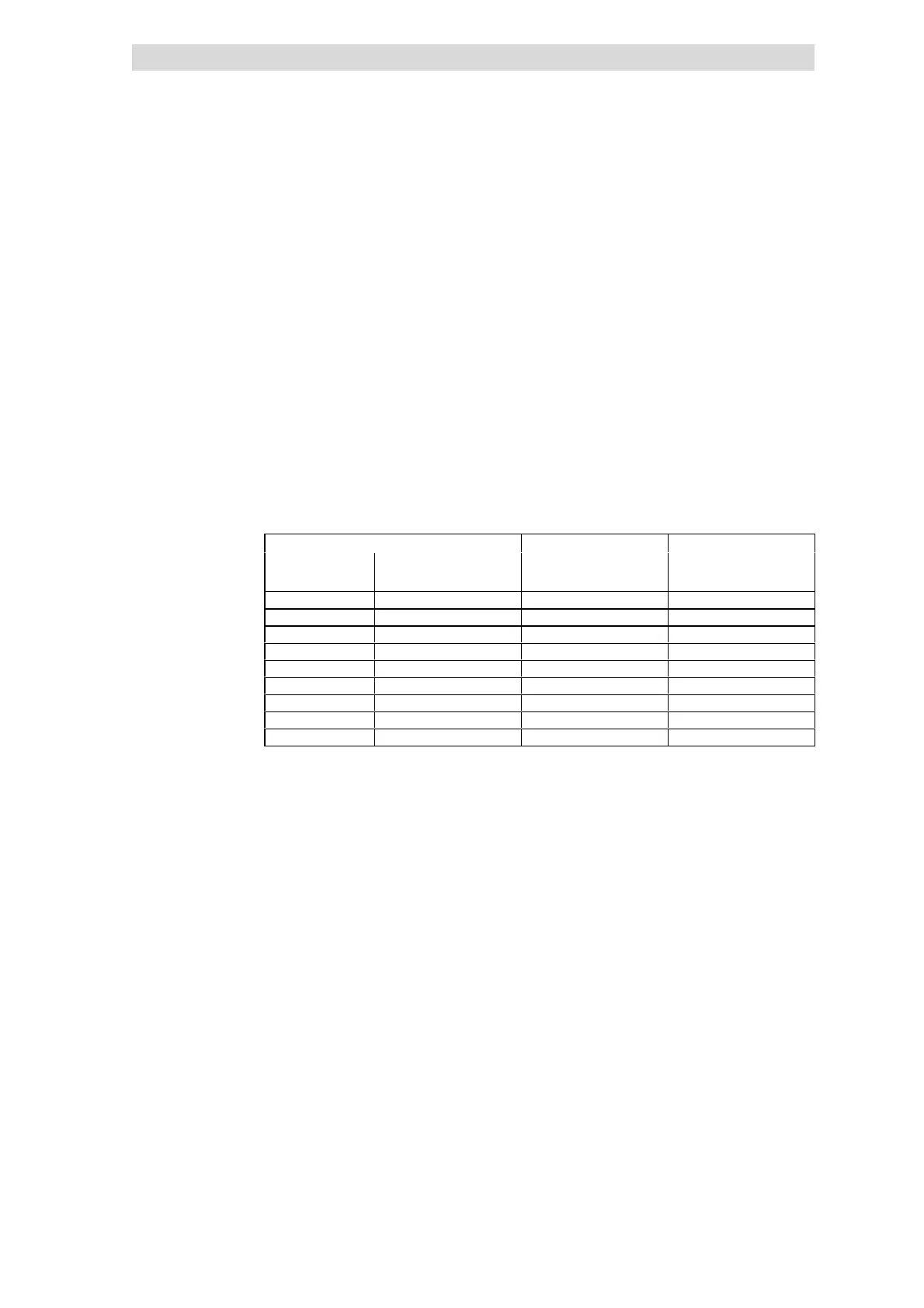
8200 vector Cooling p ath Ground
Power to be dissipated Heatsink - environment
Type P
loss
[W] R
th
[°C/W] [kg]
E82CV302K2C 110 ≤ 0.23 2.4
E82CV402K2C 150 ≤ 0.23 2.4
E82CV552K2C 205 ≤ 0.13 3
E82CV752K2C 270 ≤ 0.13 3
E82CV302K4C 110 ≤ 0.23 2.4
E82CV402K4C 140 ≤ 0.23 2.4
E82CV552K4C 190 ≤ 0.23 3
E82CV752K4C 255 ≤ 0.13 3
E82CV113K4C 360 ≤ 0.13 3
l Ambient temperature - controllers
– The rated data and the derating for higher temperatures still apply for the
ambient temperature of the drive controller.
l Heat distribution between common heatsinks/coolers within the control
cabinet
– If you mount several components (drive controller, brake units etc.) on a
common cooler, then care must be taken that the temperature of the
controller heatsinks does not exceed 75 °C.
Requirements on the cooler
Environmental conditions
 Loading...