Operating mode
V/f char acteristic control
10
Function library
10.3
10.3.1
L
10.3-7
EDS82EV903-1.0-11/2002
Load-independent boost of the motor voltage for output frequencies below the
V/f rated frequency. This serves to optimise the torque behaviour.
C0016 must always be adapted to the asynchronous motor used. Otherwise, the
motor might be destroyed by overtemperature or the controller might be driven
with overcurrent:
1. Operate the motor in idle running at slip frequency (f ≈ 5Hz):
−
f
s
Slip frequency [Hz]
f
s
= f
r
⋅
n
rsyn
− n
r
n
f
r
Rated motor frequency according to nameplate [Hz]
rsyn
r
rsyn
Synchronous motor speed [min
-1
]
f
r
⋅ 60 r
r
Rated motor speed according to nameplate [min
-1
]
n
rsyn
=
p
p Number of pole pairs
2. V
min
until the following motor current is reached:
A) Motor in short-term operation at 0 Hz ≤ f ≤ 25 Hz:
– Motor with integrated ventilation: I
motor
≤I
r motor
– Motor with forced ventilation: I
motor
≤I
r motor
B) Motor in continuous operation at 0 Hz ≤ f ≤ 25 Hz:
– Motor with integrated ventilation: I
motor
≤ 0,8 ¡ I
r motor
– Motor with forced ventilation: I
Motor
≤ I
r motor
)
))
) Note!
For adjustment, observe the thermal performance of the
connected asynchronous motor at low output frequencies:
l As experience shows it is possible to operate standard
asynchronous motors with insulation class B for a short time
with rated current 0 Hz ≤ f ≤ 25 Hz.
l Contact the motor manufacturer for exact setting values for the
max. permissible motor current in the lower frequency range of
self-ventilated motors.
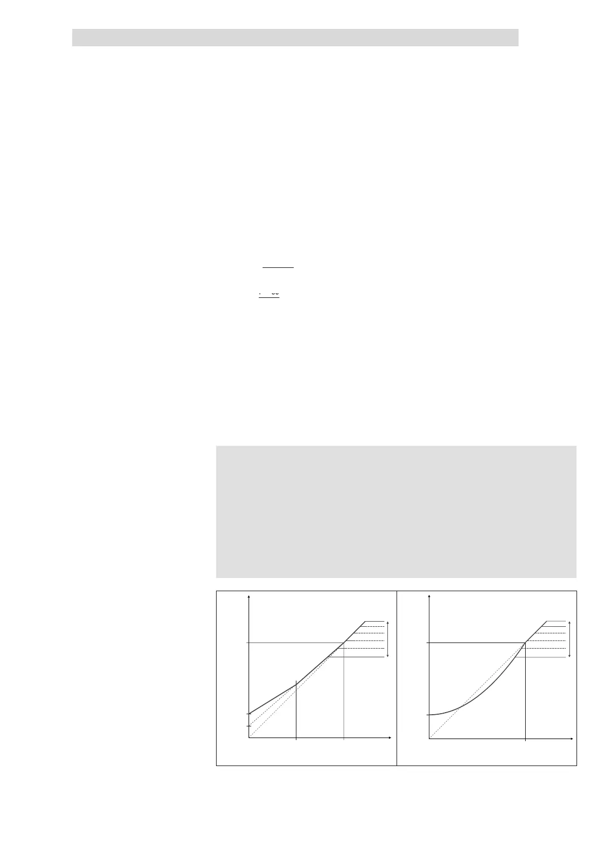
C0015
C0016
C0015
2
C0016
2
V [V]
out
f [Hz]
V
(100 %)
rmot
1/N/PE AC 264 V
3/PE AC 264 V
3/PE AC 550 V
1/N/PE AC 180 V
3/PE AC 100 V
3/PE AC 320 V
C0015
C0016
V [V]
out
f [Hz]
V
(100 %)
rmot
1/N/PE AC 264 V
3/PE AC 264 V
3/PE AC 550 V
1/N/PE AC 180 V
3/PE AC 100 V
3/PE AC 320 V
8200vec537 8200vec538
Fig. 10.3-3 Umin boost at linear and square-law V/f characteristic
Setting of V
min
boost
 Loading...