Parameter setting with the XT EMZ9371BC keypad
Installation and commissioning
9
Parameter setting
9.4
9.4.2
L
9.4-2
EDS82EV903-1.0-11/2002
9.4.2 Installation and commissioning
YZ
y
z
T
V
S
U
d
ABbc
p
S
H
P
R
G
P
a
r
a
C
o
d
e
M
e
n
u
0
0
5
0
00
5
0
.
0
0
_
H
z
MCTRL-NOUT
E82ZWLxxx
YZ
y
z
T
V
S
U
dABbc
p
SHPRG
Para
Code
Menu
0050
00
50.00_Hz
MCTRL-NOUT
E82ZBBXC
EMZ9371BC
YZ
y
z
T
V
S
U
dABbc
p
SHPRG
Para
Code
Menu
0050
00
GLOBAL DRIVE
Init
YZ
y
z
T
V
S
U
d
0050
00
50.00 Hz
20 %
YZ
y
z
T
V
S
U
d
0050
00
50.00 Hz
20 %
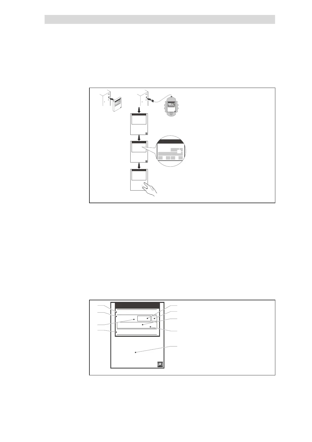
9371BC018
Fig. 9.4-1 Installation and commissioning of XT EMZ9371BC keypad or E82ZBBXC diagnosis
terminal
Connect keypad on the front of the controller to the AIF interface.
It is possible to connect the keypad and remove it during operation.
As soon as the keypad is supplied with voltage, it carries out a short self-test.
The operation level indicates, when the keypad is ready for operation:
0 Current state of the controller
1 Memory location 1 of the user menu (C0517):
Code number, subcode number, and current value
2 Active fault message or additional status signal
3 Current value in % of the status display defined in C0004
V must be pressed to leave the operation level
9.4.3 Display elements and function keys
YZ
y
z
T
V
S
U
dABbc
p
SHPRG
Para
Code
Menu
0050
00
50.00_Hz
MCTRL-NOUT
0
1
3
4
5
6
7
8
2
399371BC002
Fig. 9.4-2 Display elements and function keys of the XT EMZ9371BC keypad
 Loading...