Basic units in the power range 0.25 ... 2.2 kW
Mounting in ”cold plate” technique
5
Basic device installation
5.3
5.3.3
L
5.3-7
EDS82EV903-1.0-11/2002
M6
4Nm
35 lbin
c
f
a1
b1
b
a
d
c1
b2
e
8200vec029
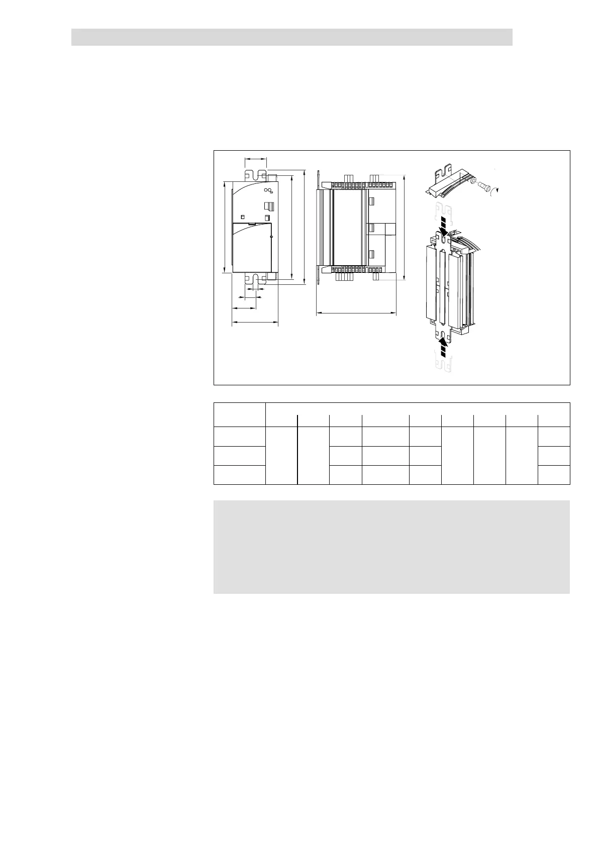
Fig. 5.3-6 Dimensions for mounting in ”Cold plate” technique 0.25 ... 2.2 kW
Dimensions [mm]
8200 vector a a1 b b1 b2 c d e f
E82CV251K2B
E82CV371K2B
150 130 ... 140 120 148
E82CV551KxB
E82CV751KxB
60 30
210 190 ... 200 180
106 6.5 27.5
208
E82CV152KxB
E82CV222KxB
270 250 ... 260 240 268
)
))
) Note!
l Apply heat-conducting paste before you bolt together the
cooler and the heatsink to keep the thermal resistance as low
as possible.
l The quantity of heat-conducting paste supplied in the delivery
package is sufficient for approx. 1000 cm
2
.
1. Slide the mounting rails into the heatsink from the top and from the bottom
2. Clean the area of contact between the heatsink and the cooler with
methylated spirits.
3. Apply a thin layer of heat-conducting paste.
4. Bolt the drive controller onto the cooler using two screws.
8200 vector 0.25 ... 2.2 kW
Mounting
 Loading...