Braking operation in a drive system
Possibilities
12
Network of several drives
12.8
12.8.1
L
12.8-1
EDS82EV903-1.0-11/2002
12.8 Braking operation in a drive system
12.8.1 Possibilities
If the braking energy created in generator operation of the drive network is not
dissipated, the voltage will be increased in the entire DC-bus. If the maximum
DC-bus voltage is exceeded, the controllers set pulse inhibit (message
”overvoltage”) and the drives idle to standstill without torque. There are different
possibilities to dissipate the generated braking energy:
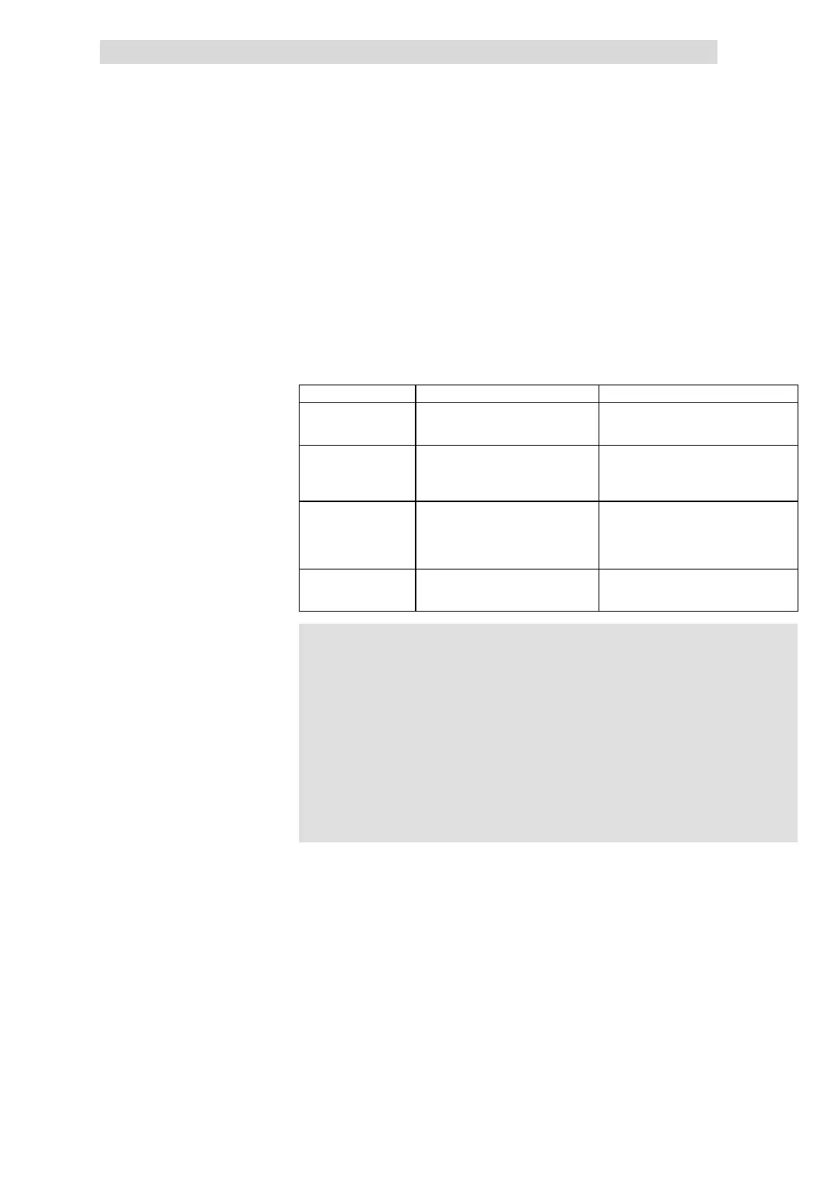
Scope of application Special features
934X regenerative
power supply unit
Long braking processes • Braking energy is fed back into supplying
mains
• No heat generation
Brake u nit 8251, 8252
or 9351
Regular braking at low power
Rare braking at medium power
• Brake resist or integrated
• No additional switching measures
required
• Example: (¶ 12.7-2)
Brake chop per 8253 or
9352
Regular braking at high power
Long braking processes at high power
• External braking resistor required
• Braking resistors can become very hot, if
necessary provide special protection
measures
• Example: (¶ 12.7-2)
Braking resistor at
controller
Regular braking at low power
Rare braking at medium power
• Only possible with 8200 vector, since t he
braking transistor is integrated
• See also: (¶ 13.4-1)
(
((
( Stop!
The network components can be destroyed, if the following is not
observed:
l Never combine the different possibilities for dissipating the
braking energy generated in the network.
l Each possibility must only be used once (e.g. do not connect
two brake modules in parallel).
l Always set the mains voltage at 93XX controllers and 935X
brake units to the same value:
– For 93XX via C0173
– For 935X via switches S1 and S2
Possibilities to dissipate braking
energy
 Loading...